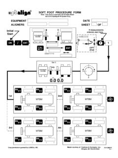
Transcription of MACHINE 1. Mount ROTALIGN SETUP ROTALIGN
1 2. Mark out four 90 positions (1, 3, 5, 7) as shown(or if shaft rotation is limited, eight 45 pos'ns, 1,2, 3, 4,..8).3. Enter dimensions :CIRCLE/SQUARE (select bolt pattern)NUMBER BOLTS (square must be 4, 8, )OPTION allows non-symmetrical flange(NORMAL ORDER clears and resumessymmetrical) Bolt Distance (diagonal diameter of bolts) Flange Diameter (diagonal diameter of flange) Coupling center to receiver4. Turn shaft to position 1, align laser andpress '1.' Turn to each position and presscorresponding key. At least 3 positions Table shows either all shim correctionsadded (+), removed (-) or for minimum movement(+/-). Select with '+/-' Turn to position '1' and press.
2 Shim as per table. Press7. Re-measure, view results and move horizontallyif vertical is in MenuVertical Machines1. Mount ROTALIGNL aseron lowermachineSTARTSTOPMOVEMACHINESETUPCOU PLINGTYPEMEASUREMODESOFTFOOTCOUPLINGTARG ETTHERMALGROWTHTOLER-ANCESSTATICFEETS elect MACHINE types: 'normal 4-feet,''6-feet,' 'single bearing,' 'V-form.' Leftmachine can be made 'short flex,' 'single plane' (solid) or'spacer shaft.' CHANGE MODE selectsthe display mode for couplingmisalignment 'Continuous sweep' (the default),'Measure at 0, 3, 6, 9,' 'Multipoint' or'Pass mode' (for uncoupled shafts).Select foot softkey & loosen bolt. Valueappears press STOP and retighten.
3 Resultsmust be carefully analyzed to determinethe correct shimming see the 'cold' coupling target alignment,based on display mode selected inCOUPLING TYPE the expected horizontal and verticalmovement for the tolerances based on RPM. PressEDIT and enter RPM. The Smiley facewill then appear in the results TABLE TYPE: 'excellent,''acceptable' or 'user-defined.' '50Hz/60Hz'shows different sets of RPM feet which cannot be moved. If leftmachine is 'Stationary ' (in MACHINESETUP above) then entire right machinemust be SETUPFILEREPORTPC-COMMPRINTER , Language, Contrast, user name, company , Open files, selected with PC using' ROTALIGN Commander' your printer from a the serial (COM) to Vertical or Horizontalmachine, or Quick :In case of 'lock-up' pressONOFFENTERCLRall select inch/mm:EDITOKMENU 2005 Printed in Wingate, NC 2005 rev.
4 4 ROTALIGN Short Instructions Norm & Bev Voelzow US Distributor LUDECA, 88th Avenue, Miami, FL 33172 Phone: 305-591-8935 Fax: 305-591-1537 Web: : & Company, Inc. Wingate, NC 28174704-233-9222 Fax 704-233-9211E-mail: Lawyers RdE3. press Measure Recheck1. Mount ROTALIGN & press2. press DimensionsTo adjust the display contrast in the Start-upScreen, press to lighten and return to the Start-up Screen at any time, ! Use theseat any timeLASER LIGHT DON'T STARE INTO BEAM CLASS II LASER PRODUCTNote:If application is for a horizontal MACHINE and youare on a horizontal MACHINE as shown, proceedto Step # you need to change the application,select orAdjust thumbwheels on laser to centerof travel.
5 Then switch on and adjustbeam onto center of receiver dustcapby sliding laser up or down on bracket to adjust for side-to-side. (Avoid using the fine adjustmentthumbwheels just yet.) Remove capand center dot on target. Check the XY Fine Adjustment: Up/down (Y-axis) use top thumb-wheel. Side-to-side (X-axis) use side shaft one complete turn(or at least 75 ).STARTSTOPRed LED Green LED Screen1. Out of rangeSteadyOff'OFF'2. Edge of rangeFast blinkFast blink'END'3. Adjustment OKOffSlow blink'OK'PressThis is a good time to check soft foot. Ofcourse, soft foot can be checked any press MoveFor Vertical or Horizontal Adjustment:a) Press then verify slow blinking green LEDon Receiver.
6 *If not in range, press andadjust laser into inner circles. Then press .VerticalLeftRightIn(Side view)machinemachinetoleranceHorizontalGa p & OffsetFront & backOut of(Top view)(symbols showfeet positionstolerancedirection)6. Recheck, go to step 3, pressIf in range, press and select or .STARTVZOOMHZOOMSTOPb) Loosen bolts and shim or move ) Re-tighten bolts and press .BOTHNote, you can view the vertical and horizontal changesimultaneously in the Move mode by pressing .For very large horizontal corrections adjust horizontallybefore press Results (Coupling)MOVE1. Coupling diameter Use 10"2.
7 Coupling center to receiver3. Receiver to front foot4. Front foot to back foot5. To use the tolerance feature, enter the RPMin the following manner. Press Menu, selectTolerances, select Table, enter : On a newalignment pressNew Mach if thereare dimensionshere already!For example press or press 9 + 3 / 4 ENTERENTERD imensions can be entered as decimals or : The optimum position toset the Laser & Receiver in theMove mode is 3 or 9 o'clock!MENUL aser is always mounted on theStationary MACHINE (your Left)Receiver is always mounted on the MACHINE To Be Moved (your Right)The Computer isnormally usedon the 9 o'clock(left) side of reference markon top of the : If you use the Beam Deflector don't forget to deduct 2"!
8 CENTERED *Version firmware will Auto Startthe Move if Centered & within 15 of12:00, 3:00, 6:00 or 9:00 position.