Transcription of Magneto Timing - San Diego Miramar College
1 Magneto Timing The two areas of Timing a Magneto are internal, and external. A number of things must occur at the same time, or in a well orchestrated sequence for the engine to function. Magneto Timing Within the Magneto the magnetic rotor must be just past neutral axis (E-Gap). The points must be just opening. And the distribution rotor must be pointed at the correct cylinder. Magneto Timing Within the engine the intake and exhaust valve must be closed. The piston/cylinder that is to fire must be close to the top of its compression stroke.
2 It must have a fresh air/fuel charge. Magneto Timing The selected wire(s) from the Magneto (s) distributor must be connected to this cylinder. And the crankshaft/ Magneto must be spinning. Magneto Timing If all of these conditions are met, the cylinder will fire. Magneto Timing Timing is initially set internally in the Magneto . It is then set to the engine. Both setting procedures may call for initial gross settings, followed by some means for fine adjustment. Magneto Timing Usually the first thing to be set is the distributor/rotor alignment.
3 Depending on the Magneto , the distributor will be indexed to the rotor shaft during initial assembly of the Magneto upper and lower housing. Magneto Timing This calls for correct alignment of the drive and driven gears. There are indicator marks for this alignment. Most can be set for either left (CCW) or right (CW) hand rotation. Magneto Timing The next step is to install the rotor/points cam. On some this can be indexed infinitely, and others it will be one or two positions depending on rotation.
4 Magneto Timing Then for most magnetos, set the rotor at the points opening position (E-Gap). Adjust the points to just open. Move rotor to maximum opening to verify the points range of operation. Magneto Timing If the points don't have the correct range of operation, even though they are in time, the coil will not charge correctly. Or the points will wear out prematurely. Magneto Timing Once E-Gap and range are within limits, auxiliary points may be adjusted. Adjustment of points will require the use of a feeler gauge, a screw driver and a degrees of rotation indicator.
5 Magneto Timing The points are secured with two screws, where one attachment is slotted. By carefully moving the slotted end with the other screw snug it can be set, and secured. Magneto Timing Magneto Timing Aircraft Magneto Operation Critical Safety Note: Treat all aircraft engines as if they were a loaded Gun Magneto grounding systems fail commonly Stay clear of the Propeller Arc Aircraft Magneto Operation Aircraft magnetos are attached to the engine case with adjustable hold down clamps or fasteners Aircraft engines use two independent magnetos Aircraft Magneto Operation The gear drive must be correctly aligned to the engine gears They have a spark lead for each cylinder To maintain proper Timing each lead must be attached to the correct
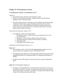
6 Cylinder Aircraft Magneto Operation Each Magneto must be set so that they spark simultaneously They must do this when the crankshaft and camshaft are in the correct position Installation and Adjustment Upon initial installation they must inserted with the drive gears correctly meshed to the engine This is done by rotating the propeller to cyl on compression stroke A Timing mark on the crankshaft or ring gear is aligned with the case split Installation and Adjustment Case Split Front of engine 2. 32.
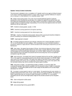
7 24. 1. T C. Cyl. No. 1 on compression stroke Timing marks Installation and Adjustment The Magneto is then set to No. 1. spark lead just firing This can be done by locating either a chamfered internal tooth, or some use an alignment pin inserted into the housing Installation and Adjustment Timing gear view hole Chamfered tooth Timing pin Timing mark Installation and Adjustment Do not rotate the crankshaft or the Magneto until all alignment jigs have been removed Installation and Adjustment Each Magneto is now installed carefully maintaining alignment Once they are both clamped snugly in place a buzz box can be used to fine tune the setting The buzzer will change tone when the internal switch just
8 Opens Installation and Adjustment The buzzer has three leads, one for each mag, and one for ground The buzzer leads are attached to the P- leads outputs on the mag Lightly tap the Magneto housing with a knuckle for fine movements. Installation and Adjustment Be sure to rotate the Magneto in a fashion that eliminates any gear or impulse coupling freeplay Set the second Magneto identical to the first unless otherwise specified Clamp each unit down and rotate propeller to verify accuracy Installation and Adjustment Often tightening magnetos will change their setting Make sure P-leads are attached and functional Once this is done attach spark plug leads in the correct locations Spark Plug Firing Order Engine firing order is
9 The sequence of spark events that must occur for all cylinders to produce power. It is established by the engine's crank &. camshaft. Spark Plug Firing Order Magneto firing order is always 1, 2, 3, 4, ? Etc. #1 mag will always go to #1 cylinder, then #2 mag goes to #3 or #4. depending on the manufacturer. Spark Plug Firing Order Cylinder numbering is set by the manufacturer. Lycoming is with #1 in front odds on the right. Continental is #1 rear odds on the right Spark Plug Firing Order Radials put #1 on top, rear bank if twin bank.
10 Odds to the rear and evens to the front in direction of crankshaft rotation. Spark Plug Firing Order For all Lycoming and Continental 4 and 6 cyl engines the firing order of the engines are the same. This is due to the difference in numbering and firing order. Spark Plug Firing Order Lycoming 4 Cyl 2 1. 4 3. Firing order = 1, 3, 2, 4. Continental 4 Cyl 4 3. 2 1. Firing order = 1, 4, 2, 3. Spark Plug Firing Order Lycoming Continental 2 1 6 5. 4 3 4 3. 6 5 2 1. 1, 4, 5, 2, 3, 6 1, 6, 3, 2, 5, 4. Spark Plug Firing Order Five, seven, and nine cylinder radials fire odds the evens.