Transcription of Manufactured Housing Anchor Installation …
1 Manufactured Housing Anchor Installation information (Updated: January 2009). Provided by TIE DOWN ENGINEERING. 010809,d12. TIE DOWN ENGINEERING 255 Villanova Drive SW Atlanta, GA 30336. (404) 344-0000 Fax (404) 349-0401. Installation information . Anchor Installation 1. Position Anchor at a slight back angle (10 ) so that when fully installed, the Anchor head will be inside any skirting or side wall. 1. 2. 3. 2. Install Anchor to +/- 2/3 depth, then install stabilizer vertically, within 3 -4 of Anchor shaft, parallel to wall of home . 3. Fully drive Anchor , attach strap (see proper strap tensioning), and pretension strap to pull Anchor rod against the stabilizer plate.
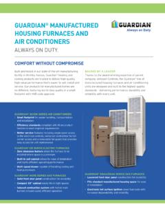
2 Manual Anchor Installation 1. Dig holes to a depth of 2/3 of the Anchor length. Install Anchor with rod or length of pipe for leverage. 2. Replace earth in hole after Anchor /plate is installed at Important: full depth. Pack dirt with a tamping rod every 6 inches of fill. Anchor must be installed to full depth. Anchor head must 3. Testing may be required in loose soil conditions to check that be at ground level or at the top of the stabilizer plate Anchor has proper holding power. which is fully installed to ground level. Electric Drive Machine Installation Operating Instructions: 1. Attach adapter head to shaft of the EDM motor, Adapter fits anchors tighten set screw.
3 And Soil Test Probe 2. Place extension handle in the end of the EDM if needed. 3. Place Anchor head into adapter, line up Anchor shaft with EDM shaft, for easier Installation . 4. Flip forward/reverse switch to forward. 5. Place Anchor tip in location where Anchor is to be buried. Hold on/off switch to install. Two man operation makes easy work of EDM Adapter Head. Anchor Installation Electric Drive Machine Cautions and Warnings: Before Installation of any ground Anchor , determine that the ground anchors to be installed will not be near any underground electrical cables, phone lines, water lines, sewer pipes, or gas lines.
4 Failure to do so may result in serious injury or death The EDM is designed for operation by two people. Do not allow the EDM to be wedged against the home or other solid objects, when operating the EDM. Electrical cord must be a minimum of 14-2 wire size w/ground up to 25 ft. of cord. Longer cords must be 12-2 wire size w/ground or lower. Never operate the EDM in wet or rainy conditions. Frayed or patched electrical cords should never be used with the EDM. Care should be taken to keep electrical cords away from anchors. Never operate drive machine without the GFI power cord. Damage to motor and injury to operator can r esult from by passing the GFI.
5 The GFI will shut off power when a ground fault is detected. The GFI will also shut off power when 010809,d12. it detects low voltage improper amps required to drive the motor. Many times the problem will be the use of an extension cord that is too long or is too light in gage. ~2~. Installation information . Stabilization Plates ABS Stabilizer Plate Class 4B Stabilizer Plate 10 x 24 . 17-1/2 x 13-1/2 Part # 59293. Galvanized: Part # 59286. 12 wide Stabilizer Plate Black Paint: Part #59292 Quik-Set Stabilizer Plate Galvanized: Part #59292G Black Paint: Part #59291. Galvanized: #59291G. Anchor Stabilizer In order to prevent lateral movement of Manufactured homes Stabilizer Plate Installation subjected to high wind loads and to comply with HUD's Wind 1.
6 Refer to any and all local, state and federal regulations. Zone I, II, & III requirements, all lateral frame ties must be 2. Use the Soil Test Probe at the Anchor location in order to attached to a properly stabilized ground Anchor . (Two approved match soil class with the (See Page 11). methods illustrated below.) 3. Partially install Anchor to allow 14 to 16 remaining above ground level. 4. Utilizing oversized hammer, vertically install stabilizer plate, nesting Anchor rod in between formed channels on outside of stabilizer plate (between Anchor and frame). Ground Level 5. Fully install Anchor so that head is at the surface of the soil (1 tolerance, if necessary) and pretension Anchor until "In Line" Installed: touching stabilizer plate.
7 Minimum Anchor length of 48". ABS Stabilizer Plate Part # 59293. 1. Determine correct Anchor to be used with the home Installation and use the manufacturer instruction for Installation , following all safety precautions. 2. Using an electric drive machine, install Anchor to a depth of approximately 28 inches at a slight back angle. 3. Dig out an 8 wide area so that the ABS stabilizer will be placed on Place ABS. undisturbed soil at a 10 to 15 degree angle toward the home . The Plate Here bottom center of the plate should be touching the Anchor rod. 4. Complete the Installation of the ground Anchor until the bottom of the Anchor head is flush with the ground.
8 5. Attach proper strap and tension strap until Anchor head is flush against the ABS plate and strap is tight. At this point, soil should be tamped into the vacant area behind the Anchor rod, tamping approximately 6 and repeating until the vacant area is flush with the surface of the surrounding ground. ~3~. Installation information . Quik-Set Stabilizer Certified Galvanized Strapping*. Installation Black Paint Part: #59291. Galvanized Part: #59291G. 10 -15 . 5" to 6". home Direction The steel strapping by Tie Down Engineering for the Manufactured Housing industry has been tested to, and conforms to, the HUD Code as referenced in Part 3280 of the 1.
9 Install ground Anchor inside skirting line at a slight back Manufactured home Construction and Safety Standards and angle of 10 - 15 . Part 3285 of the Installation standards; Final Rule. 2. While Anchor head is still 5 to 6 above ground level: install Quik Set stabilization plate around Anchor shaft, referring to (f), (b2) Anchoring Equipment Load the direction imprinted on the top of the plate. Resistance. Anchoring equipment shall be capable of resisting an 3. Install ground Anchor until Quik-Set plate is fully set. allowable working load equal to or exceeding 3,150 pounds and Hammering may be required at the corners to insure plate shall be capable of withstanding a 50 percent overload (4,725.)
10 Being fully driven. pounds total) without failure of either the anchoring 4. Install strap(s) to Anchor head and pretension according to equipment or the attachment point on the Manufactured home . approved methods. Maximum Anchor load in conjunction (g), (b2) Anchoring Equipment . with the Quik-Set device is 4725 lbs. (ultimate). Weatherization. Anchoring equipment exposed to weather- ing shall have a resistance to weather deterioration at least equivalent to that provided by a coating of zinc on steel of not Deep Set Anchor /Stabilizer Instructions less than ounces per square foot of surface coated, and in accordance with the following: 1.