Transcription of MASONRY STRUCTURES CONFINED WITH CONCRETE …
1 2720. MASONRY STRUCTURES CONFINED with CONCRETE BEAMS AND. COLUMNS. Da-hai LIU1 And Mao-zheng WANG2. SUMMARY. While a lot of unreinforced MASONRY buildings collapsed, several multistorey buildings in CONFINED MASONRY damaged slightly in the past earthquakes in China. Based on the results of additional model experiments, the CONFINED MASONRY and concentrated reinforced MASONRY STRUCTURES have been widely applied to the low-rise and medium-rise buildings respectively in the seismic zone. For the low-rise buildings the reinforced CONCRETE ring beams are placed at each floor and the post- cast tie columns are placed at each intersections of interior and exterior MASONRY walls. For the medium-rise buildings in addition to the ring beams and tie columns, the post-cast reinforced CONCRETE intermediate columns and horizontal belts are placed in all the MASONRY walls at spacing of 2~3m and 1~ respectively.
2 Model experiments and engineering practices show that the concentrated MASONRY STRUCTURES have a good strength, deformability, seismic reliability and can be applied to the multistorey buildings up to 10 stories in the seismic zones. INTRODUCTION. Seismic zones are spreaded widely in the world. MASONRY wall STRUCTURES are the main structural type in the construction of the buildings. However unreinforced MASONRY buildings are easily to be destroyed under the action of earthquake. Therefore it is very important to take countermeasures to improve the horizontal load bearing capacity and aseismic reliability of the MASONRY buildings EARTHQUAKE DAMAGES. In recent thirty years there were several severe earthquakes occurred in China. In these seismic zones a lot of brick MASONRY buildings were damaged. The brick MASONRY walls and the wall branches between the windows and doors were cracked diagonally, and the exterior walls of MASONRY buildings were collapsed out of plane.
3 If the MASONRY buildings were strengthened by reinforced CONCRETE ring beams at every floor level. The collapse of the exterior wall out of plane is prevented, and the diagonal cracks on the interior transverse walls were restricted within the story height. In seismic zone with scale intensity of 10 degree, some 3 to 8-storied brick MASONRY buildings were strengthened with reinforced CONCRETE tie beams at every floor level and tie-columns at every intersection of interior and exterior walls. These CONFINED MASONRY buildings performed very well, only a few small cracks appeared in the walls, no collapse of walls were occurred. 1. China Northwest Building Design Insitute, China. 2. China Northwest Building Design Insitute, China. CONFINED MASONARY STRUCTURES . In CONFINED MASONRY STRUCTURES the manner of the concentrated reinforcement is adopted. The meaning of concentrated reinforcement is related to the uniformly distributed reinforcements in the MASONRY .
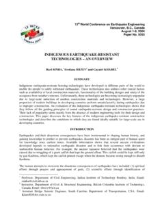
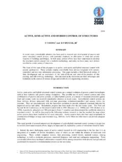
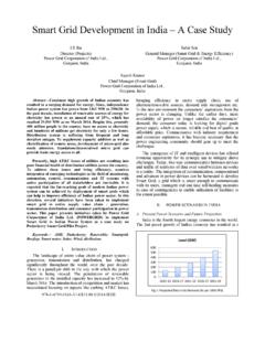
4 The distributed reinforcements in the section of wall are collected and encased in the CONCRETE . Thus the tie-columns, ring beams and horizontal reinforced belts are formed in the MASONRY walls. In CONFINED MASONRY buildings, the reinforced CONCRETE tie-columns are placed at every intersection of the longitudinal and transverse walls, the intermediate tie-columns are placed at the spacing of 2 ~ 3malong the longitudinal and transverse walls. Ring beams are placed at every floor lever along all the walls, the horizontal reinforced CONCRETE belts are placed at the spacing of ~ in the interior walls and at the spacing of ~. in the wall branches of the exterior walls. The internal perspective view of one room is as shown in Figure 1. Ring beams RC belts Tie-columns Ring beams Tie-columns Figure 1: Perspective view in one room of CONFINED MASONRY buildings STRUCTURAL EXPERIMENTS.
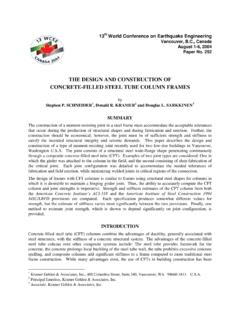
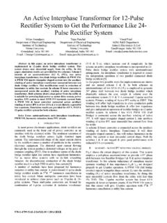
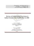
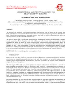
5 Reinforced CONCRETE Belts The construction of wall panel is that one or two reinforced CONCRETE belts are placed at middle or one-third point of the wall height (Figure 2). Experimental result shows that the diagonal cracks across the wall was prevented, the cracks on the wall surface is restricted within the area between the belts. Experimental result shows also that on the increment of the horizontal bearing capacity of the wall, the reinforced CONCRETE belts is better than the mortar joint reinforcements. Cracks Ring beams F F. Tie-column RC belt Figure 2 : Cracks on the wall panel strengthened with RC belt 2 2720. Intermediate Columns In addition to the tie columns at the intersections of the walls, one or two intermediate columns are placed at the middle or one-third points along the length of the wall (Figure 3 and figure 4). They are post-casted in cavity resulting from the arrangement of the MASONRY wall sectors.
6 Under the action of the low-cycle horizontal loadings with the certain vertical loadings, experiment data show that owing to the CONFINED action of the terminal and intermediate tie-columns in the wall, both the horizontal and vertical load bearing capacities of the wall increase evidently. It gives a better practical method on the improvement of the ductility and bearing capacity of the MASONRY buildings. F F F F'. 1 1. 3. 4 2 4. 2. Figure 3 Cracks on the wall panel Figure 4 Cracks on the wall panel with 3 RC Tie Columns. with 4 RC Tie Colums. ENGINEERING PRACTICES. Structural Design For the 8-storied MASONRY building in the seismic zone, bearing walls are made of perforated brick units. As compared with solid brick units, the self-weight is reduced about 25%. Roof and each floor are made of the precasted hollow slabs, and encased with reinforced CONCRETE ring beams.
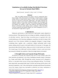
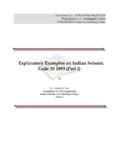
7 All the longitudinal and transverse walls are CONFINED with the reinforced CONCRETE tie-columns, ring beams and horizontal reinforced CONCRETE belts (Figure 5). Ring beams Tie-columns RC belts RC belts Underground ring beams Figure 5 : Vertical cross section of 8-storied CONFINED MASONRY building Layout of Tie-columns On the ground floor to 5-th story, the post-casted reinforced CONCRETE tie-columns are located at all the intersections of longitudinal walls and transverse walls, and also located at an interval of about 3 metres along 3 2720. the axes of the internal longitudinal and transverse load-bearing walls. Figure 6 shows the structural plan of the ground floor. Tie - columns Tie - columns Figure 6 : Layout of tie-columns on the ground floor Layout of Reinforced Belts At the floor slab levels of ground floor to 8-th story and also the roof, the reinforced CONCRETE ring beams cast-in- situ and are located along all the longitudinal and transverse load-bearing walls (Figure 5).
8 At the first and second story, the horizontal reinforced CONCRETE belts are placed at the 1/3 and 2/3 story height along all the longitudinal and transverse load-bearing walls. For the wall branches between windows along the exterior walls, the belts are placed at the 1/3 and 2/3 points of the window height. At the third and fourth story, the horizontal reinforced CONCRETE belts along all the longitudinal and transverse walls and the wall branches between windows reduce to one layer (Figure 5). CONSTRUCTION DETAIL. Tie-columns Reinforced CONCRETE tie-columns are the main structural members to confine the MASONRY wall in order to increase the horizontal and vertical load-bearing capacities, deformation ability and aseismic reliability. It may be divided into wall terminal tie-columns and wall intermediate tie-columns. It is poured after the make of MASONRY walls in the pre-formed vertical channels of the walls.
9 The width of the cross-section of the tie-columns is equal to the thickness of the walls. The longitudinal steel bars may be 4 12 0r 4 14 and with 6. horizontal stirrups at the spacing of 200mm. Its construction details are as shown in Figure 7 and Figure 8. Figure 7 : Construction details of terminal tie-columns 4 2720. Figure 8 : Intermediate tie-columns 5. Ring Beams Reinforced CONCRETE ring beams at the floor slab levels are also the main CONFINED structural members of the MASONRY walls. The ring beams along the interior load-bearing walls may be located just below the bottom of the fabricated pre-cast hollow floor slabs. The ring beams along the exterior walls is around and located at the same level of the roof slabs in order to prevent the slide displacement of the slabs during earthquake. The longitudinal steel bars of the ring beams may be 4 10 or 4 12 and with its end inserted into the tie-columns with an enough anchoraged length.
10 The joints of the ring beams are shown as in Figure 9. Figure 9 : Joints of the reinforced CONCRETE ring beams Reinforced CONCRETE Belts on the Interior Walls According to the story height and the amount of the horizontal shear force, one layer or two layers of the reinforced CONCRETE belt may be placed in the interior load-bearing walls. It is located at 1/2 or 1/3 and 2/3 story height respectively (Figure 10). RC Belts on the Walls between Windows In order to prevent the diagonal cracks on the walls between widows, two or three layers of the reinforced CONCRETE belts should be placed on the walls between windows according to the story height and the intensity of earthquake (figure 11). The reinforced CONCRETE vertical edge ribs placed at two sides of walls between windows (figure 12) are also effective. 5 2720. Figure 10 : Joints of the reinforced CONCRETE ring beams Figure 11 : RC belts on walls Figure 12 : RC edge ribs of walls Between windows between windows CONCLUSIONS.