Transcription of MCh/Mgh s D DC-DC C - Interpoint - DC/DC …
1 FEATURES Small footprint, in2 ( cm2) - MCH Surface mount package - MGH Operating temperature -55 C to +125 C 12 to 50 volt input Transient protection 80 volts for up to 120 ms 70 volts for 15 volt single and dual models Fully isolated, magnetic feedback Fixed frequency switching Inhibit function Short circuit protection Undervoltage lockout Up to 79% efficiency, typicalDESCRIPTIONThe Interpoint MCH Series and MGH Series of DC-DC converters offers up to watts of power in a low profile package. The MCh/Mgh converters are manufactured in our fully certified and qualified MIL-PRF-38534 Class H production facility and are packaged in hermetically sealed steel cases.
2 They are ideal for use in programs requiring high reliability, small size, and high efficiency. The wide input voltage range of 12 to 50 volts accepts the varying voltages of military, aerospace, or space bus power and tightly regulates output voltages to protect downstream components. Transient protection of 80 volts for up to 120 milliseconds exceeds the requirements of MIL-STD-704A for the 5 and 12 volt single models and the 5 and 12 volt dual models. The 15 volt single and dual converters will withstand transients of up to 70 volts for up to 120 MCH and MGH converters are offered with standard screening, /ES, or /883 (MIL-PRF-38534 Class H).
3 See Table 12 on page 13 and Table 13 on page 14. Standard microcircuit drawings (SMD) are available. See Table 3 on page 3 and Table 8 on page DesignMCH Series and MGH Series of DC-DC converters incorporate a continuous flyback topology with a constant switching frequency of approximately 370 kHz. Current-mode pulse width modulation (PWM) provides output voltage regulation. Output error voltage is magnetically fed back to the input side of the PWM to regulate output voltage. Regulation is also affected by the load; refer to Table 10 on page 7 and Table 11 on page 8. Dual models regulate the negative output with magnetic coupling to the positive output.
4 Up to 80% of the total load may be on one output providing that the other output carries a minimum of 20% of the total load. The dual models can be used at double the output voltage by connecting the load between positive and negative outputs, leaving the common unconnected. (ex: MCH2805D can be used as a 10 volt output.)inhibit FunCtionMCH and MGH converters provide an inhibit terminal that can be used to disable internal switching, resulting in no output voltage and an input current as low as mA. The converter is inhibited when the inhibit pin is pulled below V and enabled when its inhibit pin is left floating. An external inhibit interface should be capable of pulling the converter s inhibit pin below V while sinking the maximum inhibit current and also allowing the inhibit pin to float high to enable the converter.
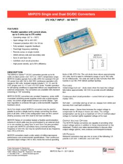
5 A voltage should not be applied to the inhibit pin. The open circuit voltage present on the inhibit pin is 7 to 12 volts. ProteCtion FeaturesUndervoltage lockout prevents the converters from operating below approximately 8 volts input voltage to keep system current levels smooth, especially during initialization or re-start operations. All models include a soft-start function to prevent large current draw and minimize overshoot. The converters also provide short circuit protection by restricting the current. MODELSVDC OutputSINGLE DUAL5 512 1215 15 Crane Aerospace & Electronics Power SolutionsMCH and MGH Single and Dual DC-DC ConvertersCrane Aerospace & ElectronicsPower Solutions Interpoint Products16706 13th Avenue West, lynnwood, WA 98037+1 1 of 14 MCH and MGH Rev AD - TO 50 VOlT input WATTN egativeOutputOutputCommonPositiveOutput+ PositiveInputInhibitFBShutdownPWMC ontrollerInputCommon+Vin+Vout++Case GroundDotted lineindicates dual modelsFigure 1.
6 MCh/Mgh bloCk DiagraMMil-stD-461 Use the Interpoint FMSA-461 (down-leaded) or FMGA-461 (surface mount, side-leaded) EMI filters to pass the CE03 requirements of - Down-leaded packageThe MCH Series converters are packaged in hermetically sealed, projection-welded steel cases which provide EMI/RFI shielding. See Figure 20 on page - Surface mount packageThe surface mount MGH DC-DC converters can be mounted with pick-and-place equipment or manually. It is recommended that the case be attached with flexible epoxy adhesive or silicone which is thermally conductive (>1 watt /meter/ K). Internal components are soldered with SN96 (melting temperature 221 C) to prevent damage during reflow.
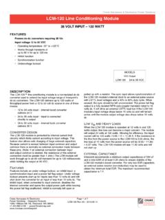
7 Maximum reflow temperature for surface mounting the MGH converter is 220 C for a maximum of 30 seconds. SN60, 62, or 63 are the recommended types of solder. Hand soldering should not exceed 300 C for 10 seconds per hermetically sealed metal cases are available in two different lead configurations. See Figure 21 on page 12 and Figure 22 on page 12. Crane Aerospace & Electronics Power SolutionsMCH and MGH Single and Dual DC-DC ConvertersPage 2 of 1412 TO 50 VOlT input and MGH Rev AD - corner and dot on top of cover indicate pin Figure 20 on page 11 for 2: MCh Pin out MCH PINS NOT IN USEI nhibitLeave unconnected No Connection pinLeave unconnectedPIN OUT MCH MODElSPinSingle OutputDual Output1 Positive input Positive input 2 input CommonInput Common3 Positive OutputPositive Output4 Output CommonOutput Common5 Case GroundCase Ground6No ConnectionNegative Output7 InhibitInhibittable 1: MCh Pin outtable 2.
8 MCh Pins not in use BOTTOM VIEW MCHSMD NUMBERS MCH MODElSStandard Microcircuit drawing (SMd)McH SiMilar Part5962-9569601 HXCMCH2805S/8835962-9569701 HXCMCH2812S/8835962-9569801 HXCMCH2815S/8835962-9570201 HXCMCH2805D/8835962-9570301 HXCMCH2812D/8835962-9570401 HXCMCH2815D/883 For exact specifications for an SMD product, refer to the SMD drawing. SMDs can be downloaded from: 3: MCh sMD nuMber Cross reFerenCeMODEl NUMBER OPTIONS to deterMine tHe Model nuMber enter one oPtion froM eacH category in tHe forM Model and input VoltageOutput Voltage Number of Outputs 1 Case Options 2 Screening 3 OPTIONSMCH05, 12, 15 SMCH down-leaded: leave blank(standard, leave blank)05, 12, 15 DES883 FIll IN FOR MODEl #4 MCH_____ _____/ Notes1.
9 Number of Outputs: S is a single output and D is a dual output2. Case Options: For the standard MCH down-leaded case leave the case option blank. For the MGH straight-lead case, leave the case option blank. For the MGH, surface mount gull-wing case, insert the letter Z in the case option position. 3. Screening: For standard screening leave the screening option blank. For other screening options, insert the desired screening level. For more information see Table 12 on page 13 and Table 13 on page If ordering MCH standard (down-leaded) case or MGH standard (straight-leaded) case by model number add a -Q to request solder dipped leads (MCH2805S/883-Q).
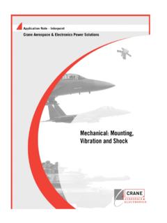
10 The MGH case Z is always 4: MCh MoDel nuMber oPtionsMCH28 12 D / 883 Base ModelInput VoltageOutput VoltageScreeningNumber of Outputs (S = single, D = dual)(R = decimal point, 3R3 = Vout)(Standard screening has no designatorin this position.)MODEl NUMBERING KEYF igure 3: MCh MoDel nuMbering key Crane Aerospace & Electronics Power SolutionsMCH and MGH Single and Dual DC-DC ConvertersPage 3 of 1412 TO 50 VOlT input and MGH Rev AD - 4: Mgh Pin out123456897181716151413121110 TOP VIEWMGH(standard case)Differently colored glass bead around pin one or dimple inheader (bottom or side of case) indicates pin marking is oriented with pin one at the upper right Figure 21 on page 12 for dimensions and gull-wing OUT MGH MODElSPinSingle OutputDual Output1 Positive input Positive Input2No ConnectionNo Connection3 input CommonInput Common4, 5 Positive OutputPositive Output6, 7 Case Ground Case Ground8, 9 Output CommonOutput Common10, 11 Case GroundCase Ground12No ConnectionNo Connection13, 14No ConnectionNegative Output15, 16, 17No ConnectionNo Connection18 InhibitInhibitMGH PINS NOT IN USEI nhibitLeave unconnected No Connection pinsConnect to case ground for best EMI performance.