Transcription of mcosmos software - willrich.com
1 Bulletin No. 2200mcosmos softwarecoordiNate measuriNg machiNescoordinate measuring machine software for all levels of users, from entry level to by mitutoyo is a proprietary metrology suite of inter-related modules and dedicated expansion modules for Microsoft Windows 7, 8 and operating systems (32 or 64-bit). Available in 37 countries and 12 different languages, mcosmos is the world's standard in metrology software . Supported by MiCAT ( mitutoyo Intelligent Computer Aided Technology), your mitutoyo CMM is streamlined with intuitive user interfaces that provide a familiar look and feel to operate multiple modules. They work together seamlessly to put reliable metrology at you fingertips throughout the entire production allows integration among a series of applications, improving the efficiency of your CMM and the productivity of your quality control functions. Specific expansion modules are available dedicated to GEOPAK or for specific applications such as GEAR measurement, airfoil analysis, reverse engineering and integrating CAD with metrology.
2 mitutoyo Controlled Open Systems for Modular Operation Support mitutoyo is the world s largest provider of measurement and inspection solutions, with the most complete, capable line of machines, systems, sensors and software . With a presence in more than 100 countries, mitutoyo is the international precision measurement technology is based on expertise acquired from around the globe, providing the assurance that you are employing best practices for managing your dimensional metrology equipment (DME).With computer technology laboratories in the United States, Europe and Asia, mitutoyo employs highly qualified specialists who are devoted to the development of one common software platform. 3experienceThe modular system allows the capability to tailor the measuring software with only the specific modules needed to meet requirements. The measurement results may be displayed, printed and archived with numerous built-in and user-defined formats.
3 software packages and expansion modules to meet your metrology production (Geometry online/offline modules) Includes: support for high-speed nominal scanning (known path) with scanning probes (optional), user-defined dialogs, parametric programming with the use of variable substitution and user-defined (3D freeform evaluation module)For the creation of measurement and evaluation routines of surfaces from a CAD model for nominal to actual comparison. Includes: automatic path generation (animated), collision checking and flexible reporting (Online/offline programming module) For the creation of measurement and evaluation routines of prismatic features (lines, planes, circles, cylinder, etc.), from a CAD model for nominal to actual comparison. Includes: MachineBuilder, automatic path generation (animated), collision checking and flexible reporting (Scanning)For the scanning and evaluation of workpiece : support for single-point/measuring probes, SP-25 continuous scanning probes, variable contour tolerances, best fit, patch scan (digitizing) and flexible reporting.
4 software package featuresMCOSMOS 1 mcosmos 2 mcosmos 3 STDOPTSTDOPTSTDOPTSTDOPTSTDOPTSTDOPTSTDO PTSTDOPTSTDOPTSTDOPTSTDOPTSTDOPTMCOSMOS LEVEL 1:Modules Included1. Geometric measurement module2. caD Prismatic Programming module3. surface analysis moduleMCOSMOS LEVEL 2:Modules IncludedMCOSMOS LEVEL 3:Modules Included1. Geometric measurement module1. Geometric measurement module2. caD Prismatic Programming module3. surface analysis module4. scanning module5. Data transfer moduleLevel 1 Geometric programming & 2add programmability from a caD 3add tools for scanning probes and reverse (basic geometry module) provides an easy graphical console with tool bars and windows, which can be personal-ized to the operator s provides visual tools and a graphically enhanced display providing step-by-step screen wizards. The design allows operators of all experience levels to easily and quickly create efficient measurement basic level software includes the flexibility for advanced tools demanded by the most experienced operators, such as looping, formula calculations or expressions that use variables, libraries of day-to-day sub-routines and conditional statements which add logic for a variety of CNCmcosmos 1 GEOPAK s program tree is simple to read and program tree can be expanded or collapsed to correspond with the operator's level or part application a double click on the function line, an easy dialog box will appear.
5 For example, a hole that is threaded may not repeat if the probe path does not follow thread CNC control, the dialog box allows a pitch value to program the probe path to follow the thread of use for entry level to expert(Figure 1) Auto Circle Measurement bythe Circular Travel FunctionArc Movement of ProbeCircular Slot MeasurementDirect Measurement of Tapped Hole5In GEOPAK there is no limit to reporting capabilities. Included templates are ideal for most applications. If a custom report is required, Protocol Designer allows the operator to customize the output to a desired Designer eliminates the need to transpose the GEOPAK results to a separate spreadsheet or document that may be required, for example, AS9102. Forms can be created and saved as templates so the data from GEOPAK auto fills the report after executing the part a template is used for output, the operator can choose a variety of formats such as Adobe PDF, Microsoft Excel and save or print the ReportingPart Security & ManagementIncluded with GEOPAK is a built-in module that fully controls the machine and the access to your parts.
6 The Part Manager displays the part list that may be stored locally on the DME computer or via the LAN to a company network drive. Within the parts list the operator can attach the setup instruction documents, header information for part traceability and images for visual Part Manager interface has complete control of GEOPAK. User profiles may be set to limit access to learn, edit or repeat, securing the system like no other package on the market. Our security meets the FDA 21 CFR Part 11 specification for electronic data storage and signatures with enhanced logon security, profiles and audit reports6 CAT-1000 facilitates the programming of measurement tasks during the GEOPAK learn mode. All data for measuring parts and tolerance evaluations are taken accurately from the CAD model via pointing device (mouse, trackball, etc.) selection. The same principles apply for programming probe paths (clearance and measurement), while at the same time, using the embedded nominal information from the CAD model for tolerance CAD InterfaceCAT-1000 utilizes Spatial s prominent 3D ACIS Modeler, which is used in more than 350 customer applications and 2 million seats fully supports and reads PMI (Product & Manufacturing Information), which is embedded in the model for datum alignment, GD&T (Geometric Dimensioning and Tolerancing).
7 Spatial s 3D InterOp delivers the highest quality data exchange between CAD formats, enabling superior CAD file translation. The comprehensive suite of translators provides import/export for all applications, including ACIS, CGM and Parasolid-based applications. 3D InterOp is embedded in many of today s leading design, engineering and manufacturing V5, SolidWorks, NX Siemens (Unigraphics), Parasolids, AutoDesk Inventor, Pro-Engineer and IGES or VDAFS exchange formats are available with CAT-1000 is ACIS (*.sat) and STEP AP203, which are both licensed copies from Spatial InterOp. Product Manufacturing InformationVirtual Offline OptionalDual Screen Optionalmcosmos 27 CMM System ManagerCMM System Manager allows you to create a virtual representation of your CMM. New mitutoyo models or legacy models, such as the FN series and BHN series, can be selected based on machine measuring size. If you have multiple machines, they can also be added for simulation or part placement purposes.
8 CAD models can be placed and compared to the true working volume of the machine and indexing probe swivel access. CAT-1000S3D surface analysis creates grid patterns to verify a surface with a single-click tool that calculates a collision-free probe path to measure a grid of surface CMMs allow the operator to move the probe manually, and the point will appear in real-time. Probe compensation is determined from the center of the stylus and the shortest distance to the CAD model to eliminate cosine deviation can be displayed as spherical points or as a gradient icons are used to show the surface vector direction of the material from the nominal and tolerance reports the deviations from the nominal profile to determine if the measured contour is within the tolerance SCANPAK Best-fit can provide the information required to correct the part. Best-fit is most effective when the reference alignment is not accurately defined to provide tool-setting graphical report template provided with SCANPAK allows the oper-ator to make comments or notes and uses Protocol Designer for making special mcosmos 3 SCANPAK constructs from the measured contour circles and/or line elements based on the user-specified tolerance amount calculated from the elements form elements automatically construct best-fit geometry (lines/circles) from a contour.
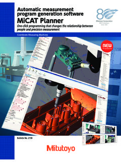
9 This information can be used as reference for the basic dimensions given for the profile call-out or even assist in reverse engineering for tool contour compared to the nominal AS IS." The areas shown in red fail to meet the profile requirement. Calculate elements automaticallyKnown path scanningCNC Gasket Scan provides an easy-to-use tool for complex planes requiring a specific measuring path on the gasket measuring path can be created by nodes or offset from the CAD model. mcosmos -3 maximizes your throughput when using a scanning probe such as the SP25 or MPP. 9micat PlannerAutomatic measurement programgeneration softwareMiCAT planner is mitutoyo s latest software development for fast and efficient CMM part programming. Operation of micat planner is easy and intuitive. Programs are made with a few mouse clicks in minutes instead of hours or :1) Load design model2) Select target CMM3) Part placement via virtual alignment4) Measurement program creation5) Translate to Geopak MCOSMOSM easurement PlanThe measurement plan is synchronized with the 3D view and the program view.
10 This allows you to select a feature in any of the views (plan view, 3D view, program view) and the feature is highlighted in the other views simultaneously. Reordering the feature measurements is possible by dragging and dropping of the features in the plan view. Users can select a feature, characteristic, or a point set in the plan view, to modify the corresponding properties in the property view as planner toolbar is workflow EditorThe Rules Editor allows users to create rules to define measurement approaches, such as number of points per feature, sensor type, fitting method and automatic sensor Model Support: Siemens NX w/PMI CATIA v5 w/PMI PRO/E w/PMI ACIS (SAT)10 DME 2 DME 3 The Pure DMISPAK module is a powerful bi-directional program exchange for legacy DMIS-based module converts the native DMIS file (*.dmi) to GEOPAK. New programs from mcosmos also can be exported to a DMI format so non- mitutoyo brand CMMs can read and execute on their legacy DMIS-based DMISPAKM easurLink acquires the measurements real-time as the CMM runs the GEOPAK Part storage can be local or networked to a SQL software manages data from all types of devices from handheld tools to CMM and supports non- mitutoyo modules for mcosmos3D surface generation software is used with Patch Scanning Generator to easily create high-accuracy surface design, using common B-Rep entities or STL file output, which are ideal for reverse 3D SurfaceSTL MeshPiston Head Reverse EngineeredPoints11expansion modules for mcosmosWith mcosmos -3, MAFIS analyzes the SCANPAK profile that is measured and outputs the evaluation results of the desired other airfoil analysis modules, which operate outside of the CMM software as a separate package.