Transcription of MD-12 Spur Gear Design
1 1P N RAO112. Spur Gear Design and selectionObjectives Apply principles learned in Chapter 11 to actual Design and selection of spur gear systems. Calculate forces on teeth of spur gears, including impact forces associated with velocity and clearances. Determine allowable force on gear teeth, including the factors necessary due to angle of involute of tooth shape and materials selected for gears. Design actual gear systems, including specifying materials, manufacturing accuracy, and other factors necessary for complete spur gear Design . Understand and determine necessary surface hardness of gears to minimize or prevent surface wear. Understand how lubrication can cushion the impact on gearing systems and cool them. Select standard gears available from stocking manufacturers or N RAO2 Standard proportions American Standard Association (ASA) American Gear Manufacturers Association (AGMA) Brown and Sharp 14 deg; 20 deg; 25 deg pressure angle Full depth and stub tooth systemsP N RAO3 Specifications for standard gear + (in.)
2 1 (in.)14 20 25 20 Pressure angle14 full depthFull depth & pitches finer than 20 Full depth & pitches coarser than 20 ItemP N RAO4 Forces on spur gear teeth Ft= Transmitted force Fn= Normal force or separating force Fr= Resultant force = pressure angle Fn= Fttan cosFFtr=P N RAO5 Forces on spur gear teeth Power, P; or Torque, T = Ftr and r = Dp/2 Combining the above we can write63,000nTP=ptDT2F=n P63,000T=P N RAO6 20-tooth, 8 pitch, 1-inch-wide, 20 pinion transmits 5 hp at 1725 rpm to a 60-tooth gear. Determine driving force, separating force, and maximum force that would act on mounting Problem 12-1: Forces on Spur Gear Teeth2P N RAO7(2-6)P = Tn63,000 T = 63,000Pn T = (63,000)51725 = 183 in-lb Find pitch circle:(11-4)Dp = NpPd Dp = 20 teeth8 teeth/in diameter = in 20-tooth, 8 pitch, 1-inch-wide, 20 pinion transmits 5 hp at 1725 rpm to a 60-tooth gear.
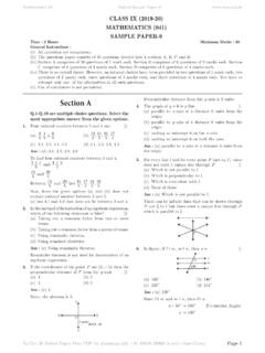
3 Determine driving force, separating force, and maximum force that would act on mounting Problem 12-1: Forces on Spur Gear TeethP N RAO8 Find transmitted force:(12-3)Ft = 2 TDp Ft = (2)183 in = 146 lb Find separating force:(12-1)Fn = Ft tan Fn = 146 lb tan 20 Fn = 53 lb Find maximum force:(12-2)Fr = Ftcos Fr = 146 lbcos 20 Fr = 155 lbExample Problem 12-1: Forces on Spur Gear Teeth (cont d.)P N RAO9 Surface Speed Surface speed (Vm) is often referred to as pitch-line speed Vm = ft/min Vm= m/min -- Metric units12nD p1000nD pP N RAO10(12-7)Vm = D nor(12-5)Vm = Dp n12 Vm = in 1725 rpm ft12 in Vm = 1129 ft/minExample Problem 12-2: Surface Speed In previous problem, determine the surface speed:P N RAO11 Strength of Gear Teeth Lewis form factor methodP N RAO12 Forces on Gear Tooth 1998 McGraw-Hill, Hamrock, Jacobson and SchmidFigure Forces acting on individual gear N RAO13 Lewis equation Fs= Allowable dynamic bending force (lb) Sn= Allowable stress (lb/in2).
4 Use endurance limit and account for the fillet as the stress concentration factor b = Face width (in.) Y = Lewis form factor (Table ) Pd= Diametral pitchdnsPbYSF=P N RAO14 Table Lewis form factors (Y)P N RAO15 Pinion:Sn = .5 Su = .5 (95 ksi) = ksi(12-9)Fs = Sn b YPd Find Lewis form factor (Y) from Table 12-1, assuming full-depth teeth:Y = .320Fs = 47,500 (1) .3208 Fs = 1900 lb In Example Problem 12-1, determine the force allowable (Fs) on these teeth if the pinion is made from an AISI 4140 annealed steel, the mating gear is made from AISI 1137 hot-rolled steel, and long life is Problem 12-3: Strength of Gear TeethP N RAO16 Gear:Sn = .5 (88 ksi) = 44 ksi(Table 12-1)Y = .421Fs = 44,000 (1) .4218 Fs = 2316 lb Use Fs = 1900 lb for Design Problem 12-3: Strength of Gear Teeth (cont d.)P N RAO17 Classes of Gears Transmitted load depends on the accuracy of the gears Gear Manufacture Casting Machining Forming Hobbing Shaping and Planing Forming stampingP N RAO18 Force Transmitted Transmitted load depends on the accuracy of the gears A dynamic load factor is added to take care of this.
5 Ft= Transmitted force Fd= Dynamic force CommercialtmdF600V600F+=4P N RAO19 Classes of Gears Carefully cut Precision Hobbed or shavedtmdF1200V1200F+= += +=P N RAO20 Design Methods Strength of gear tooth should be greater than the dynamic force; Fs Fd You should also include the factor of safety, NsfdsfsFNF P N RAO21 Table Service FactorsHeavy < Nsf< 2 Moderately heavy < Nsf< shock, frequent < Nsf< load without shock1 < Nsf< N RAO22 Face width of Gears Relation between the width of gears and the diametral <<bP N RAO23 If, in Example Problem 12-1, the gears are commercial grade, determine dynamic load and, based on force allowable from Example Problem 12-3, would this be an acceptable Design if a factor of safety of 2 were desired? Use surface speed and force transmitted from Example Problems 12-2 and 12-3. Dynamic load:Example Problem 12-4: Design Methods This Design meets the )146(6001129600600600=+=+= Comparing to force allowable:lblblbFNFdsfs42195042121900> (12-10)P N RAO24 Therefore:Sn =.
6 5 SuSn = .5 (55 ksi) = ksi Find Dp :(11-4)Dp = NpPd Dp = 2412 = 2 in Spur gears from the catalog page shown in Figure 12-3 are made from a .2% carbon steel with no special heat treatment. What factor of safety do they appear to use in this catalog? Try a 24-tooth at 1800 rpm gear for example purposes. From Appendix 4, an AISI 1020 hot-rolled steel would have .2% carbon with an Sy= 30 ksi and Su= 55 Problem 12-5: Design Methods5P N RAO25 Find Vm :(12-5)Vm = Dp n12 Vm = 2 in (1800 rpm) ft12 in Vm = 942 ft/min Find Fs :(12-9)Fs = Sn b YPd (from Table 12-1)Y = .302Fs = 27,500 ( ) .30212 Fs = 519 lbExample Problem 12-5: Design Methods (cont d)P N RAO26 Set Fs = Fd and solve for Ft :Fd = Fs = 600 + Vm600 Ft519 lb = 600 + 942600 FtFt = 202 lb(12-3)T = F Dp2 T = 202 lb 2 in2 T = 202 in-lb(2-6)P = Tn63,000 = 202 (1800)63,000 = hpor(12-6)P = Ft Vm33,000 = 202 (942)33,000 = hpExample Problem 12-5: Design Methods (cont d)P N RAO27 Compared to catalog:Nsf = hp - calculatedhp - catalog Nsf = = Problem 12-5: Design Methods (cont d) Appears to be reasonable value.
7 Manufacturer may also have reduced its rating for wear purposes as these are not hardened N RAO28 Miscellaneous properties:(11-4)Dp = NpPd = 4812 = 4 inNg = Np Vr = 48(3) = 144 teeth Pair of commercial-grade spur gears is to transmit 2 hp at a speed of 900 rpm of the pinion and 300 rpm for gear. If class 30 cast iron is to be used, specify a possible Design for this problem. The following variables are unknown: Pd, Dp, b, Nt, Nsf, . As it is impossible to solve for all simultaneously, try the following: Pd= 12, Nt= 48, = 14 , Nsf= 2 Solve for face width Problem 12-6: Design MethodsP N RAO29 Surface speed:(12-5)Vm = Dp n12 Vm = 4 in 900 rpm12 in/ft Vm = 943 ft/min Finding force on teeth:(12-6)Ft = 33,000 hpVm Ft = 33,000 (2)943 Ft = 70 lbExample Problem 12-6: Design Methods (cont d.)P N RAO30 Example Problem 12-6: Design Methods (cont d.)lbFFFVF ddtmd18070600943600600600= += += Dynamic force Since width bis the unkown:ddsfndnsdsfsFPNYbSPYbSFandFNF== Class 30 CI; Su= 30 ksi; Sn=.
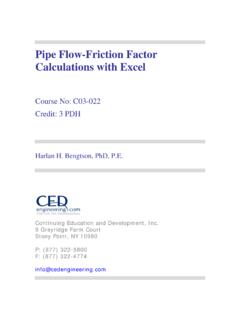
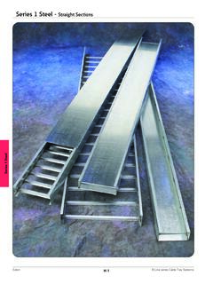
8 4 Su(.4 is used because cast iron): Sn= 12 ksi Y = .344(12-10)(12-8)(Table 12-1)6P N RAO31 Substituting:(12-9)Sn b YNsf Pd = Fd12,000 b .3442 (12) = 180b = inches Check ratio of width to pitch:(12-14)8Pd < b < 812 < 1 < .66 < 1 < Problem 12-6: Design Methods (cont d.) This is an acceptable Design . Many other designs are also N RAO32 To increase the dynamic beam strength of the gear Increase tooth size by decreasing the diametral pitch Increase face width upto the pitch diameter of the pinion Select material of greater endurance limit Machine tooth profiles more precisely Mount gears more precisely Use proper lubricant and reduce contaminationP N RAO33 Buckingham Method of Gear Design It offers greater flexibility Expected error is based on different-pitch teeth More conservative designP N RAO34 Fig. Expected error in tooth profilesP N RAO35 Table Values of C for e = inch8301,1401,6608001,1001,600 Gray iron and Gray ironGray iron and steelSteel and steel20 deg14 degMaterialP N RAO36 Buckingham Method of Gear )FC( )FC( ++++=7P N RAO37 Fig.
9 Recommended maximum error in gear teethP N RAO38(Appendix 4)Su = 95 ksiSn = .5 Su = .5(95 ksi) = ksi(11-4)Dp = NpPd = 2416 = in A pair of steel gears is made from annealed AISI 3140. Each gear has a surface hardness of BHN = 350. The pinion is a precision, 16 pitch, 20 involute, with 24 teeth 1 inch wide. The gear has 42 teeth. To transmit 3 hp at a speed of 3450 rpm for a safety factor of , is this a suitable Design ?Example Problem 12-7: Buckingham Method of Gear Design and Expected ErrorP N RAO39 Find torque:(2-6)P = Tn63,000 T = P (63,000)n T = 3 (63,000)3450 T = 55 in-lb Find force transmitted:(12-3)Ft = 2 TDp Ft = 2(55 in-lb) in Ft = 73 lbExample Problem 12-7: Buckingham Method of Gear Design and Expected Error (cont d.)P N RAO40 Find surface speed:(12-5)Vm = Dp n12 Vm = in 3450 rpm12 ft/in Vm = 1355 ft/min Find force allowable (Fs):(12-9)Fs = Sn b YPd (from Table 12-1)Y =.
10 337Fs = 47,500 (1) .33716 Fs = 1000 Example Problem 12-7: Buckingham Method of Gear Design and Expected Error (cont d.)P N RAO41 Example Problem 12-7: Buckingham Method of Gear Design and Expected Error (cont d.) Expected error from Figure 12-4:e = .0005 The value of Cfrom Table 12-3 for steel and steel and 20 involute angle gears is 1660:C = .0005 (1000) 1660C = 830 Solve for dynamic load using Buckingham s equation: This meets the )738301()1355(05.)738301()1355( )(05.)( > =+ ++ +=++++=dsfsddtmtmtdFNFlbFFFbCVFCbVFF(12- 15)P N RAO42 Wear strength (Buckingham) +=gpggPWDDD2 KbDFFw= tooth wear strength (lb)Dp= diametral pitch of pinion (in.)Dg= diametral pitch of gear (in.)b = face width (in.)Kg= load stress factor (Appendix 13)8P N RAO43 Wear formula:(12-16)Fw = Dp b Q Kg Find Q :(12-17)Q = 2 NgNg + Np Q = 2 (42)42 + 24 Q = (from Appendix 13)Kg = 270 In prior example problem, verify the surface is suitable for wear wear use Nss= Problem 12-8: Wear of GearsP N RAO44 Example Problem 12-8: Wear of Gears (cont d.)