Transcription of Measuring Temperature with RTDs – A Tutorial
1 _____Product and company names are trademarks or trade names of their respective Copyright 1996 National Instruments Corporation. All rights 1996 Application Note 046 Measuring Temperature withRTDs A TutorialIntroductionA resistance- Temperature detector (RTD) is atemperature sensing device whose resistance increaseswith Temperature . An RTD consists of a wire coil ordeposited film of pure metal. RTDs can be made ofdifferent metals and have different resistances, but themost popular RTD is platinum and has a nominalresistance of 100 at 0 are known for their excellent accuracy over awide Temperature range.
2 Some RTDs have accuraciesas high as ( C) at 0 C. RTDs are alsoextremely stable devices. Common industrial RTDsdrift less than C/year, and some models are stableto within can be difficult to measure because they haverelatively low resistance (100 ) that changes onlyslightly with Temperature (less than / C). Toaccurately measure these small changes in resistance,you may need to use special configurations thatminimize errors from lead wire an RTD is a passive resistive device, youmust pass a current through the device to produce ameasurable voltage.
3 This current causes the RTD tointernally heat, which appears as an error. Selfheating is typically specified as the amount of powerthat willraise the RTD Temperature by 1 C, or 1 mW/ C. Youcan minimize self heating by using the smallestpossible excitation current. The amount of selfheating also depends heavily on the medium in whichthe RTD is immersed. An RTD can self heat up to100 times higher in still air than in moving Relationship ofResistance andTemperature in RTDsCompared to other Temperature devices, the output ofan RTD is relatively linear with respect totemperature.
4 The Temperature coefficient, called alpha( ), differs between RTD curves. Although variousmanufacturers may specify alpha differently, alpha ismost commonly defined as the change in RTDresistance from 0 to 100 C, divided by the resistanceat 0 C, divided by 100 C: ( / / C) = (R100 - R0)/(R0 * 100 C)where R100 is the resistance of the RTD at 100 C,and R0 is the resistance of the RTD at 0 example, a 100 platinum RTD with = will measure at 100 1 displays a typical resistance-temperaturecurve for a 100 platinum ( C)Resistance ( )Figure 1.
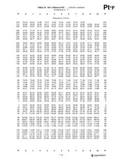
5 Resistance- Temperature Curve for a 100 platinum RTD, = the resistance- Temperature curve isrelatively linear, accurately converting measuredresistance to Temperature requires curve fitting. TheCallendar-Van Dusen equation is commonly used toapproximate the RTD curve:Rt = R0[1 + At + Bt2 + C(t - 100)3]where Rt is the resistance of the RTD attemperature = t, R0 is the resistance of the RTD at0 C, A, B, and C are the Callendar-Van Dusencoefficients shown in Table 1, and t is thetemperature in C. For temperatures above 0 C, theC coefficient equals 0.
6 Therefore, for temperaturesabove 0 C, this equation reduces to a quadratic. Ifyou pass a known current, IEX, through the RTD andmeasure the output voltage developed across theRTD, V0, you can solve for t:t=2(V0 IEXR0)IEXR0[A+A2+4B(V0 IEXR0)/IEXR0]where V0 is the measured RTD voltage and IEX is theexcitation platinum RTD curves follow one of threestandardized curves the DIN 43760 standard( = ), the Industrial or Americanstandard ( = ), or the InternationalTemperature Scale (ITS-90) that is used with wire-wound RTDs ( = ).
7 The Callendar-VanDusen coefficients for each of these three platinumRTD curves are listed in Table Measurement CircuitsBecause the RTD is a resistive device, you mustdrive a current through the device and monitor theresulting voltage. However, any resistance in thelead wires that connect your measurement system tothe RTD will add error to your readings. Forexample, consider a two-wire RTD elementconnected to a measurement system that also suppliesa constant current source, IEX, to drive the shown in Figure 2, the voltage drop across thelead resistance, RL, adds to the measured voltage.
8 + -RLV0 RTIEXRLF igure 2. Two-Wire RTD MeasurementFor example, a lead resistance of in each wire,RL, adds a error to the resistance a platinum RTD with = , the resistanceequals a /( / C) = C you are using lead lengths greater than 10 ft, youwill probably need to compensate for this leadresistance. The preferred RTD measurement methodis to use a four-wire RTD. One pair of wires carriesthe current through the RTD; the other pair senses thevoltage across the RTD. Because only negligiblecurrent flows through the sensing wires, the leadresistance error of RL2 and RL3 is negligible.
9 Thisconfiguration is illustrated in Figure 3. +RL2V0 RTRL4RL1RL3-IEXF igure 3. Four-Wire RTD MeasurementTable 1. Callendar-Van Dusen Coefficients Corresponding to Common RTDsStandardTemperatureCoefficient ( )AB C*DIN x x x x x x x x x 10-12* For temperatures below 0 C only; C = for temperatures above 0 reduce costs, you may instead want to use a three-wire RTD. By using the three-wire RTD in aWheatstone configuration with a current source, asshown in Figure 4a, you can compensate for the leadresistances.
10 Notice that, in this bridge configuration,the effects of RL1 and RL3 cancel each other outbecause they are located in opposite arms of thebridge. Lead resistance RL2 does not add significanterror because little current flows through , you can use a current excitation sourceand connect the three-wire RTD as shown inFigure 4b. In this configuration, the resistance ofonly one lead, RL1, adds error to the measurement. RL2 RTRL1RL3R1R2R3+V0a. Three-Wire RTD in a Wheatstone Configuration-IEX +RL2V0 RTRL1RL3b. Three-Wire RTD with a Current Excitation Source-IEXF igure 4.