Transcription of A Basic Guide to RTD Measurements
1 1 SBAA275 June2018 SubmitDocumentationFeedbackCopyright 2018,TexasInstrumentsIncorporatedA BasicGuideto RTDM easurementsApplicationReportSBAA275 June2018A BasicGuideto RTDM easurementsJosephWuABSTRACTRTDs,or resistancetemperaturedetectors,are sensorsusedto amongthe mostaccuratetemperaturesensorsavailable, ,gettingaccuratemeasurementswithprecisio nanalog-to-digitalconverters(ADCs)requir esattentionto detailin designof measurementcircuitsand calculationof the an overviewof the RTD,discussingtheirspecifications,constr uction,and detailsin theiruse in shownwitha basicdesignguide,showingcalculationsnece ssaryto determinethe ADCsettings,limit measurementerrors,and verifythat the designfits in theoperatingrangeof the of Figures1PT100 RTDR esistanceFrom 200 C to 850 200 C to 850 ,Three-Wire,and a IDAC2to Chopthe , , , ,Low-SideReferenceMeasurementCircuitWith One , , SeriesTwo-WireRTD.
2 SeriesFour-WireRTD, of (qC)RTD Resistance (:) June2018 SubmitDocumentationFeedbackCopyright 2018,TexasInstrumentsIncorporatedA BasicGuideto RTDM easurements1 RTDO verviewRTDsare resistiveelementsthat changein resistanceis well characterized,they are usedto makeprecisiontemperaturemeasurements,wit h capabilityofmakingmeasurementswith accuraciesof well C. RTDsare typicallyconstructedfroma lengthof wire wrappedarounda ceramicor also be constructedfromthickfilm resistorsplatedontoa wire or resistanceis typicallyplatinumbut may also be PT100is a commonRTDconstructedfromplatinumwith a resistanceof 100 at 0 C.
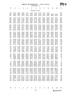
3 RTDelementsare also availablewith 0 C resistancesof 200,500,1000,and 2000 . relationshipbetweenplatinumRTDresistance and temperatureis describedby the Callendar-VanDusen(CVD) showsthe resistancefor temperaturesbelow0 C and Equation2showsthe resistancefor temperaturesabove0 C for a T < 0: RRTD(T) = R0 {1 + (A T) + (B T2) + [(C T3) (T 100)]}(1)For T > 0: RRTD(T) = R0 [1 + (A T) + (B T2)](2)The coefficientsin the Callendar-VanDusenequationsare definedby the theresistanceof the RTDat 0 C. For a PT100 RTD,R0is 100.
4 For IEC 60751standardPT100 RTDs,thecoefficientsare: A = 10-3 B = 10-7 C = 10-12 The changein resistanceof a PT100 RTDfrom 200 C to 850 C is displayedin PT100 RTDR esistanceFrom 200 C to 850 CWhilethe changein RTDresistanceis fairlylinearoversmalltemperatureranges,F igure2 displaystheresultingnon-linearityif an end-pointfit is madeto the curveshownin (qC)Nonlinearity Error (:) June2018 SubmitDocumentationFeedbackCopyright 2018,TexasInstrumentsIncorporatedA BasicGuideto RTDM easurementsFigure2. PT100 RTDNon-LinearityFrom 200 C to 850 CThe resultsshowa non-linearitygreaterthan16 , makinga temperaturesgreaterthan0 C, temperaturescan be determinedby solvingthe quadraticfromEquation2.
5 For temperatureslowerthan0 C, the thirdorderpolynomialof Equation1 may be ,determiningthe temperaturemay be computationallydifficultandusinga look-uptableto determinethe temperatureis morecalculationaccuracyusinghigherorderp olynomialsoversegmentedtemperatureranges ,but the Callendar-VanDusenequationremainsa meansthat thereis little variationfromsensorto sensorbecauseof allowsfor goodmeasurementaccuracy,evenif RTDsensorsarereplacedfromsystemto two tolerancestandardsthat definea gradeor classfor Americanstandardis ASTME1137and is usedmostlyin Europeanstandardis knownas theDIN or IEC IEC 60751is accuracyof the RTDstartingwith a baseresistanceof 100 at a temperatureof 0 showsthe specificationsof differentclassesof bothstandards,the RTDhas the tightesttoleranceat 0 C.
6 An absoluteerroris combinedwith a proportionalerrorthat has a temperaturecoefficient.(1)1/10 DIN is not includedin the IEC 60751specificationbut is an industryacceptedtolerancefor is 1/10thof the DIN IEC ClassB RTDT oleranceClassInformationTOLERANCETOLERAN CEVALUES( C)RESISTANCEAT 0 C( )ERRORAT 100 C( C)ASTMG radeB ( + |T|)100 ( + |T|)100 ClassC ( + |T|)100 ClassB ( + |T|)100 ClassA ( + |T|)100 ClassAA ( + |T|)100 (1) ( + |T|)100 specifiedtemperaturerangeof eachRTDclasstolerancebecomessmallerwith moreaccurategradesand ,the rangevarieswith the moredetailsabouttolerancevaluesand temperatureranges,consultthe datasheetsof the RTDmanufacturer.
7 ADCRRTDRREFIDAC1 REFPREFNLead 1 Lead 2 Lead 2 Lead 1 Lead 3 Lead 1 Lead 4 Lead 2 Lead June2018 SubmitDocumentationFeedbackCopyright 2018,TexasInstrumentsIncorporatedA BasicGuideto madein threedifferentwiringconfigurationsdescri bedin this differentexcitationand circuittopologyto reducethe shownin Two-Wire,Three-Wire,and Four-WireRTDsIn the two-wireconfiguration,the RTDis connectedthroughtwo wiresconnectedto eitherend of the this configuration,the lead wire resistancescannotbe separatedfromthe RTDresistance,addinganerrorthat cannotbe separatedfromthe leastaccurateRTDmeasurementsand are usedwhenaccuracyis not criticalor whenlead lengthsare the the three-wireconfiguration,the RTDis connectedto a singlelead wire on one end and two lead wireson the Measurements ,lead resistanceeffectscaneffectivelybe cancelled,reducingthe errorin lead wireresistanceassumesthat the lead the four-wireconfiguration,two lead wiresare connectedto eitherend of the this configuration.
8 The RTDresistancemay be measuredwith a four-wireresistivemeasurementwith driventhroughone lead on eitherend,whilethe RTDresistanceis measuredwith theotherlead on this measurement,the RTDresistanceis sensedwithouterrorcontributedfromthe lead wire reactingwith the mostaccuratemeasurements,but are the an ADCare typicallymadewith a showsthebasictopologyof a the ADCwith a two-wireRTDand a referenceresistorRREF. A singleexcitationcurrentsource(IDAC1)is usedto excitethe RTDas well as to establishareferencevoltageacrossRREFfor the Exampleof a RatiometricRTDM easurement June2018 SubmitDocumentationFeedbackCopyright 2018,TexasInstrumentsIncorporatedA BasicGuideto RTDM easurementsWithIDAC1,the ADCmeasuresthe voltageacrossthe RTDusingthe voltageacrossRREFas providesan outputcodethat is proportionalto the ratioof the RTDvoltageand thereferencevoltageas shownin Equation3.
9 Ratiometricmeasurementswill only producepositiveoutputdata, a fully-differentialmeasurement,this is only the positivehalf of thefull-scalerangeof the ADC,reducingthe measurementresolutionby one bit. The followingequationsassumea 24-bitbipolarADC,with VREFas the full-scalerangeof the 223 VRTD/ VREF= 223 IIDAC1 RRTD/ (IIDAC1 RREF)(3)The currentscancelso that the equationreducesto Equation4:Outputcode= 223 RRTD/ RREF(4)In the end,the RTDresistancecan be representedfromthe codeas a functionof the Outputcode RREF/ 223(5)The measurementdependson the resistivevalueof the RTDand the referenceresistorRREF, but not onthe ,the absoluteaccuracyand temperaturedrift of the excitationcurrentdoesnot a ratiometricmeasurement,as long as thereis no currentleakagefromIDAC1outsideof this circuit,the measurementdependsonly on RRTDand RREF.
10 ADCconversionsdo not needto betranslatedto ADChas a low gain error,RREFis oftenthe largestsourceof referenceresistormustbe a high accuracyprecisionresistorwith low errorin the referenceresistancebecomesagain errorin the Figure5, the lead resistancesof a three-wireRTDare shownand a secondexcitationcurrentsourceisadded, Exampleof LeadWireResistanceCancellationWitha singleexcitationcurrentsource,RLEAD1adds an errorto the addingIDAC2,thesecondexcitationcurrentso urceis usedto cancelout the errorin the lead wire lead resistancesand the secondcurrentsource,the equationbecomes:Outputcode= 223 [IIDAC1 (RRTD+ RLEAD1) (IIDAC2 RLEAD2)] / [(IIDAC1+ IIDAC2) RREF](6)If the lead resistancesmatchand the excitationcurrentsmatch,thenRLEAD1= RLEAD2and IIDAC1= IIDAC2.