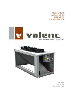
Transcription of MECHANICAL INSTALLATION OPERATION & …
1 M E C H A N I C A L I N S TA L L A T I O N O P E R A T I O N & M A I N T E N A N C E VPR Series VPRC/P Series VPRE Series VPRX Series March 2014 Part Number 472916 VPR, VPRC/P, VPRE, VPRX Series IOM 2 March 2014 Technical Support: (800) 789-8550 Part Number 472916 Table of Contents Table of Contents .. 2 Safety .. 3 Special Design Requests .. 3 Model Number Guide .. 4 Clearances .. 5 Lifting Procedure .. 6 INSTALLATION .. 8 Pad INSTALLATION .. 8 Curb 8 Curb & Ductwork Dimensions .. 9 Outdoor Air Hood Assembly .. 11 Duct & Drain Connections .. 11 Condensate Drain Connection .. 11 Duct Connections .. 12 Electrical, Gas, and Water Connections .. 13 Electrical Connections.
2 15 Gas Connections .. 15 Refrigeration and Gas Connections Indoor Unit .. 16 Pressure Testing the System .. 17 Chilled Water Coil Freeze Protection .. 17 Refrigeration System Setup .. 18 Water Source Heat 18 Air Source Heat Pump .. 20 Wiring .. 20 Field-Mounted Sensors .. 20 maintenance .. 22 Troubleshooting .. 25 Motor .. 25 25 Controls .. 27 Startup Documentation .. 29 Job Information .. 29 Startup Checklist .. 30 Air-Cooled Direct Expansion Startup Form .. 31 Water Source Heat Pump Startup Form .. 33 Air Source Heat Pump with Supplemental Heat Startup Form .. 35 Cleaning Instructions for Enthalpy Plate .. 38 Warranty .. 39 41 VPR, VPRC/P, VPRE, VPRX Series IOM 3 March 2014 Technical Support: (800) 789-8550 Part Number 472916 Safety WARNING: Improper INSTALLATION , adjustment, service, maintenance , or alteration can cause property damage, personal injury, or loss of life.
3 INSTALLATION , startup, and service must be performed by a qualified installer, service agency, or gas supplier. The customer must provide proper equipment and fully-trained installers to follow local safety requirements when receiving, installing, or servicing equipment. Consult all local building, electrical, occupational safety, and gas codes. Lock out all power supplies before servicing the unit to prevent accidental startup. All fan blades should be secured to prevent wind rotation. Remove any restrictive device before restoring power. The Clean Air Act of 1990 bans the intentional venting of refrigerant (CFC and HCFC) as of July 1, 1992. Approved methods of recovery, recycling, or reclaiming refrigerant must be followed.
4 Fines and/or incarceration may be levied for non-compliance. Special Design Requests VPR, VPRC/P, VPRE, and VPRX units are occasionally built with special features requested by the customer. This manual does not reflect any Special Design Requests and only covers standard options. VPR, VPRC/P, VPRE, VPRX Series IOM 4 March 2014 Technical Support: (800) 789-8550 Part Number 472916 Model Number Guide VPR, VPRC/P, VPRE, VPRX Series IOM 5 March 2014 Technical Support: (800) 789-8550 Part Number 472916 Clearances The minimum allowable clearances around each unit are as follows. Failure to abide by these minimum clearances may prevent serviceability or affect unit performance.
5 110/210/310 casings 36"away from all sides of the unit 350/450 casings 48" away from all sides of the unit VPR, VPRC/P, VPRE, VPRX Series IOM 6 March 2014 Technical Support: (800) 789-8550 Part Number 472916 Lifting ProcedureLifting Guidelines Crane lift only. Preparation of curb and roof openings should be completed prior to lifting unit to the roof. Lifting lugs consist of integral U-bolts located at the top of the unit. Unit must be lifted using all lifting lugs on the exterior of the unit. Cables or chains should be at least double the length of the unit to prevent stress on the structure. Spreader bars are required for lifting the unit to prevent damage to the cabinet.
6 Do not use belt-type slings. Chain angle at point of lug connection must never exceed 20 degrees from vertical in any direction. Always test-lift the unit to check for proper balance and rigging before hoisting to desired location. Do not twist the unit while it is being lifted. WARNING: Failure to follow proper instructions could result in property damage, serious injury, or death. Never lift units in windy conditions. Lifting Lug Quantities Casing VPR VPRX VPRE VPRC/P 110 4 4 6 8 210 4 4 6 8 310 4 4 6 8 350 6 6 8 10 450 6 6 N/A N/A VPR, VPRC/P, VPRE, VPRX Series IOM 7 March 2014 Technical Support: (800) 789-8550 Part Number 472916 CRANE LIFT ONLY USE ALL PROVIDED LIFTING LUGS (UNITS MAY HAVE FEWER LIFTING LUGS THAN SHOWN BELOW) USE SPREADER BAR TO PREVENT DAMAGE TO UNIT CHAIN ANGLE AT POINT OF LUG MUST NEVER EXCEED 20 FROM VERTICAL TEST LIFT UNIT TO CHECK FOR PROPER BALANCE AND RIGGING NEVER LIFT IN WINDY CONDITIONS 471551 VPR, VPRC/P, VPRE, VPRX Series IOM 8 March 2014 Technical Support.
7 (800) 789-8550 Part Number 472916 INSTALLATION Receiving and Inspection Visually inspect the unit before unloading and note any damage in writing on the delivery receipt. If the unit is damaged during shipping, the customer should immediately file a claim with the shipping company and notify the manufacturer. Photograph the damage if possible. Verify that all pieces listed on the bill of lading have been received. Storage Any unit stored outdoors prior to INSTALLATION should be covered. Do not store other equipment on top of or inside the unit. Temporary Use This equipment must not be used as: Temporary heating or cooling Construction heating The units should not be operated until construction is complete and the units have properly undergone the pre-startup and startup routines.
8 IMPORTANT: The bottom of the unit must be field-insulated if outdoor air can contact the bottom of the unit. To avoid leakage, do not drill or punch holes in the floor of the unit. Hanging INSTALLATION DO NOT permanently suspend the unit from the lifting lugs. If the unit is to be hung, additional supports are required under the unit. Hang the unit from the supports, making sure the unit is level. Failure to keep the unit level will result in operational problems. Pad INSTALLATION Check to make sure the pad is level. Failure to provide a level surface will result in operational problems. Check for correct orientation of the unit. Lift unit into place per the lifting instructions in this manual.
9 Secure the unit to the pad in accordance with all applicable building codes. Curb INSTALLATION IMPORTANT: Gasket material must be applied to all surfaces of the curb which contact the unit to create proper seal between the unit and the curb. Ensure that the roof curb is level. Failure to level the curb will result in operational problems. Lift unit into place per the lifting instructions in this manual. Ensure a neoprene gasket is installed on the top flange of the perimeter and cross members of the curb. Check for correct orientation of the unit on the curb. Check the seal between the roof curb and the unit. Apply additional caulking as required. Failure to provide an adequate seal can result in air and water leakage into the building.
10 Secure the unit to the curb in accordance with all applicable building codes. Specifications Factory-supplied roof curbs shall be constructed of 16 gauge G-90 galvanized steel and fully assembled at the factory. A " wood nailer shall be provided around the entire perimeter of the curb. Curb shall be fully insulated through " fiberglass insulation. Cross-member supports shall be provided for connecting ductwork prior to the unit being set on the roof. Duct Connections When the supply air discharge opening and/or the return air intake opening are located on the bottom of a VPR, VPRC/P, VPRE, or VPRX series unit, the ductwork should be connected to the curb directly.
