Transcription of Mechanical System Elements
1 MechatronicsPhysical Modeling -MechanicalK. Craig1 Mechanical System Elements Three basic Mechanical Elements : spring (elastic) element Damper (frictional) element Mass (inertia) element Translational and rotational versions These are passive (non-energy producing) devices Driving Inputs force and motion sources which cause Elements to respond MechatronicsPhysical Modeling -MechanicalK. Craig2 Each of the Elements has one of two possible energy behaviors: stores all the energy supplied to it dissipates all energy into heat by some kind of frictional effect spring stores energy as potential energy Mass stores energy as kinetic energy Damper dissipates energy into heat Dynamic response of each element is important step response frequency responseMechatronicsPhysical Modeling -MechanicalK. Craig3 spring Element Real-world design situations Real-world spring is neither pure nor ideal Real-world spring has inertia and friction Pure spring has only elasticity -it is a mathematical model, not a real device Some dynamic operation requires that spring inertia and/or damping not be neglected Ideal spring : linear Nonlinear behavior may often be preferable and give significant performance advantagesMechatronicsPhysical Modeling -MechanicalK.
2 Craig4 Device can be pure without being ideal ( , nonlinear spring with no inertia or damping) Device can be ideal without being pure ( , device which exhibits both linear springiness and linear damping) Pure and ideal spring element: Ks= spring stiffness (N/m or N-m/rad) 1/Ks= Cs= compliance (softness parameter)()()s12ss12sfKxxKxTKK= == = ssxCfCT= =KsxffxCsMechatronicsPhysical Modeling -MechanicalK. Craig5 Energy stored in a spring Dynamic Response: Zero-Order Dynamic System Model Step Response Frequency Response Real springs will not behave exactly like the pure/ideal element. One of the best ways to measure this deviation is through frequency Modeling -MechanicalK. Craig6 spring Element()()()0sxs02s02s0 Work Done fdxKxdxKxdxKx2Cf2===== MechatronicsPhysical Modeling -MechanicalK. Craig7 Frequency ResponseOfSpring Elements ()()0s0ffsintxCfsint= = MechatronicsPhysical Modeling -MechanicalK. Craig8 Zero-Order Dynamic System ModelStep ResponseFrequency ResponseMechatronicsPhysical Modeling -MechanicalK.
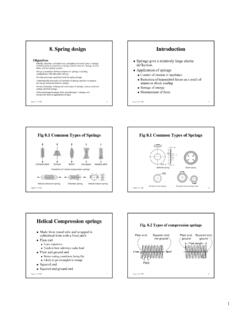
3 Craig9 More Realistic Lumped-Parameter Model for a SpringKsKsMBBf, xMechatronicsPhysical Modeling -MechanicalK. Craig10 Linearization for a Nonlinear spring ()()()000220002xxxx00xxxxdfdfyf(x) xxdx2!dxdfyyxxdx=== =+ ++ + L()000xxdfyyxxdx yKx= + =MechatronicsPhysical Modeling -MechanicalK. Craig11 Real Springs nonlinearity of the force/deflection curve noncoincidence of the loading and unloading curves (The 2ndLaw of Thermodynamics guarantees that the area under the loading f vs. xcurve must be greater than that under the unloading f vs. xcurve. It is impossible to recover 100% of the energy put into any System .)MechatronicsPhysical Modeling -MechanicalK. Craig12 Several Types of Practical Springs: coil spring hydraulic (oil) spring cantilever beam spring pneumatic (air) spring clamped-end beam spring ring spring rubber spring (shock mount) tension rod spring torsion bar springMechatronicsPhysical Modeling -MechanicalK. Craig13 spring -like Effects in Unfamiliar Forms aerodynamic spring gravity spring (pendulum) gravity spring (liquid column) buoyancy spring magnetic spring electrostatic spring centrifugal springMechatronicsPhysical Modeling -MechanicalK.
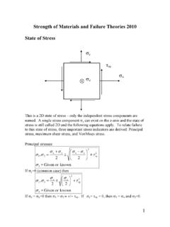
4 Craig14 Damper Element A pure damper dissipates all the energy supplied to it, , converts the Mechanical energy to thermal energy. Various physical mechanisms, usually associated with some form of friction, can provide this dissipative action, , Coulomb (dry friction) damping Material (solid) damping Viscous dampingMechatronicsPhysical Modeling -MechanicalK. Craig15 Pure / ideal damper element provides viscous friction. All Mechanical Elements are defined in terms of their force/motion relation. (Electrical Elements are defined in terms of their voltage/current relations.) Pure / Ideal Damper Damper force or torque is directly proportional to the relative velocity of its two = = 12dddTBBdtdtdt = = MechatronicsPhysical Modeling -MechanicalK. Craig16 Forces or torques on the two ends of the damper are exactly equal and opposite at all times (just like a spring ); pure springs and dampers have no mass or inertia. This is NOT true for real springs and dampers. Units for B to preserve physical meaning: N/(m/sec) (N-m)/(rad/sec) Transfer Function()2222dxdxDx Dxdtdtxx(x)dt xdtdtDD @@@@DifferentialOperatorNotationMechatro nicsPhysical Modeling -MechanicalK.
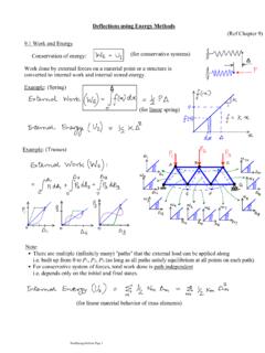
5 Craig17 Operational Transfer Functions We assume the initial conditions are zero. Damper element dissipates into heat all Mechanical energy supplied to it. Force applied to damper causes a velocity in same ()()()()fTDBD DBDxx11D DfBDTBD @@@@()()2dxdxPowerforcevelocityfBdtdt == @MechatronicsPhysical Modeling -MechanicalK. Craig18 Power input to the device is positive since the force and velocity have the same sign. It is impossible for the applied force and resulting velocity to have opposite signs. Thus, a damper can never supply power to another device; Power is always positive. A spring absorbs power and stores energy as a force is applied to it, but if the force is gradually relaxed back to zero, the external force and the velocity now have opposite signs, showing that the spring is delivering power. Total Energy Dissipated()()2dxdxPdtBdtBdxfdxdtdt === MechatronicsPhysical Modeling -MechanicalK. Craig19 Damper ElementStep Input Forcecauses instantly a Step of dx/dtand a Ramp of xMechatronicsPhysical Modeling -MechanicalK.
6 Craig20 Frequency ResponseofDamper Elements ()()()0t0000ffsintdxBdt1xxfsintd tBf1costB= = = = 0xf0fA1 BAfB == MechatronicsPhysical Modeling -MechanicalK. Craig21 Sinusoidal Transfer Function M is the amplitude ratio of output over input is the phase shift of the output sine wave with respect to the input sine wave (positive if the output leads the input, negative if the output lags the input)()x1 DfBD=Di ()x1iMfiB == ()x11iM90fiBB == = MechatronicsPhysical Modeling -MechanicalK. Craig22 Real Dampers A damper element is used to model a device designed into a System ( , automotive shock absorbers) or for unavoidable parasitic effects ( , air drag). To be an energy-dissipating effect, a device must exert a force opposite to the velocity; power is always negative when the force and velocity have opposite directions. Let s consider examples of realintentional Modeling -MechanicalK. Craig23 Viscous (Piston/Cylinder) DamperA relative velocity between the cylinder and piston forces the viscous oil through the clearance space h, shearing the fluid and creating a damping = = fluid viscosityMechatronicsPhysical Modeling -MechanicalK.
7 Craig24 Simple Shear DamperAndViscosity Definitionfluid viscosityshearing stressF/Avelocity gradientV/t =@@2 AFVtF2 ABVt = ==MechatronicsPhysical Modeling -MechanicalK. Craig25 ExamplesofRotary Dampers3 DLB4t =40DB16t =MechatronicsPhysical Modeling -MechanicalK. Craig26 Commercial Air Damperlaminar flowlinear dampingturbulent flownonlinear damping(Data taken with valve shut)Air Damper much lower viscosity less temperature dependent no leakage or sealing problemMechatronicsPhysical Modeling -MechanicalK. Craig27 Eddy-Current Damper Motion of the conducting cup in the magnetic field generates a voltage in the cup. A current is generated in the cup s circular path. A current-carrying conductor in a magnetic field experiences a force proportional to the current. The result is a force proportional to and opposing the velocity. The dissipated energy shows up as I2R heating of the Modeling -MechanicalK. Craig28 Temperature SensitivityOfDamping MethodsMechatronicsPhysical Modeling -MechanicalK.
8 Craig29 Other ExamplesofDamper FormsMechatronicsPhysical Modeling -MechanicalK. Craig30 The damper element can also be used to represent unavoidable parasiticenergy dissipation effects in Mechanical systems. Frictional effects in moving parts of machines Fluid drag on vehicles (cars, ships, aircraft, etc.) Windage losses of rotors in machines Hysteresis losses associated with cyclic stresses in materials Structural damping due to riveted joints, welds, etc. Air damping of vibrating structural shapesMechatronicsPhysical Modeling -MechanicalK. Craig31 Hydraulic Motor Friction and its ComponentsMechatronicsPhysical Modeling -MechanicalK. Craig32 Inertia Element A designer rarely inserts a component for the purpose of adding inertia; the mass or inertia element often represents an undesirable effect which is unavoidable since all materials have mass. There are some applications in which mass itself serves a useful function, , accelerometers and Modeling -MechanicalK. Craig33 Useful ApplicationsofInertiaFlywheels are used as energy-storage devices or as a means of smoothing out speed fluctuations in engines or other machinesAccelerometerMechatronicsPhysica l Modeling -MechanicalK.
9 Craig34 Newton s Law defines the behavior of mass Elements and refers basically to an idealized point mass : The concept of rigid body is introduced to deal with practical situations. For pure translatory motion, every point in a rigid body has identical motion. Real physical bodies never display ideal rigid behavior when being accelerated. The pure / ideal inertia element is a model, not a real object.()()forcesmassacceleration= MechatronicsPhysical Modeling -MechanicalK. Craig35 Rigid and FlexibleBodies:Definitions and BehaviorMechatronicsPhysical Modeling -MechanicalK. Craig36 Newton s Law in rotational form for bodies undergoing pure rotational motion about a single fixed axis: The concept of moment of inertia Jalso considers the rotating body to be perfectly rigid. Note that to completely describe the inertial properties of any rigid body requires the specification of: Its total mass Location of the center of mass 3 moments of inertia and 3 products of inertia()()torquesmoment of inertiaangular acceleration= MechatronicsPhysical Modeling -MechanicalK.
10 Craig37 Rotational InertiaJ (kg-m2)()()()()()tangential forcemassacceleration2rLdrr == ()R22320 RMRtotal torque2 LrdrRLJ22= = = = MechatronicsPhysical Modeling -MechanicalK. Craig38 Moments of InertiaForSome Common ShapesMechatronicsPhysical Modeling -MechanicalK. Craig39 How do we determineJfor complex shapes with possibly different materials involved? In the design stage, where the actual part exists only on paper, estimate as well as possible! Once a part has been constructed, use experimental methods for measuring inertial properties. How?MechatronicsPhysical Modeling -MechanicalK. Craig40 Experimental MeasurementOfMoment of Inertia()222s22s20n0snnndtorquesJJdtdKJd tKd0dtJcost (0)K rad/secJf cycles/sec2 = = = + = = = &@@s22nKJ4f= MechatronicsPhysical Modeling -MechanicalK. Craig41 Actually the oscillation will gradually die out due to the bearing friction not being zero. If bearing friction were pure Coulomb friction, it can be shown that the decay envelope of the oscillations is a straight line and that friction has no effect on the frequency.