Transcription of Membrane Bioreactors factsheet
1 wastewater Management Fact Sheet 1 Membrane Bioreactors INTRODUCTION The technologies most commonly used for per-forming secondary treatment of municipal wastewater rely on microorganisms suspended in the wastewater to treat it. Although these tech-nologies work well in many situations, they have several drawbacks, including the difficulty of growing the right types of microorganisms and the physical requirement of a large site. The use of microfiltration Membrane Bioreactors (MBRs), a technology that has become increas-ingly used in the past 10 years, overcomes many of the limitations of conventional systems.
2 These systems have the advantage of combining a sus-pended growth biological reactor with solids removal via filtration. The membranes can be designed for and operated in small spaces and with high removal efficiency of contaminants such as nitrogen, phosphorus, bacteria, bio-chemical oxygen demand, and total suspended solids. The Membrane filtration system in effect can replace the secondary clarifier and sand fil-ters in a typical activated sludge treatment system. Membrane filtration allows a higher biomass concentration to be maintained, thereby allowing smaller Bioreactors to be used.
3 APPLICABILITY For new installations, the use of MBR systems allows for higher wastewater flow or improved treatment performance in a smaller space than a conventional design, , a facility using secon-dary clarifiers and sand filters. Historically, membranes have been used for smaller-flow sys-tems due to the high capital cost of the equipment and high operation and maintenance (O&M) costs. Today however, they are receiving increased use in larger systems. MBR systems are also well suited for some industrial and commercial applications.
4 The high-quality efflu-ent produced by MBRs makes them particularly applicable to reuse applications and for surface water discharge applications requiring extensive nutrient (nitrogen and phosphorus) removal. ADVANTAGES AND DISADVANTAGES The advantages of MBR systems over conven-tional biological systems include better effluent quality, smaller space requirements, and ease of automation. Specifically, MBRs operate at higher volumetric loading rates which result in lower hydraulic retention times. The low reten-tion times mean that less space is required compared to a conventional system.
5 MBRs have often been operated with longer solids residence times (SRTs), which results in lower sludge pro-duction; but this is not a requirement, and more conventional SRTs have been used (Crawford et al. 2000). The effluent from MBRs contains low concentrations of bacteria, total suspended solids (TSS), biochemical oxygen demand (BOD), and phosphorus. This facilitates high-level disinfec-tion. Effluents are readily discharged to surface streams or can be sold for reuse, such as irrig-tion. The primary disadvantage of MBR systems is the typically higher capital and operating costs than conventional systems for the same through-put.
6 O&M costs include Membrane cleaning and fouling control, and eventual Membrane re-placement. Energy costs are also higher because of the need for air scouring to control bacterial growth on the membranes. In addition, the waste sludge from such a system might have a low settling rate, resulting in the need for chemicals to produce biosolids acceptable for disposal (Hermanowicz et al. 2006). Fleischer et al. 2005 have demonstrated that waste sludges from MBRs can be processed using standard tech-nologies used for activated sludge processes.
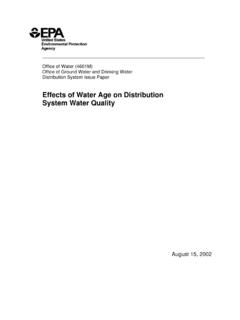
7 2 Membrane FILTRATION Membrane filtration involves the flow of water-containing pollutants across a Membrane . Water permeates through the Membrane into a separate channel for recovery (Figure 1). Because of the cross-flow movement of water and the waste constituents, materials left behind do not accu-mulate at the Membrane surface but are carried out of the system for later recovery or disposal. The water passing through the Membrane is called the permeate, while the water with the more-concentrated materials is called the con-centrate or retentate.
8 Figure 1. Membrane filtration process (Image from Filter) Membranes are constructed of cellulose or other polymer material, with a maximum pore size set during the manufacturing process. The require-ment is that the membranes prevent passage of particles the size of microorganisms, or about 1 micron ( millimeters), so that they remain in the system. This means that MBR systems are good for removing solid material, but the re-moval of dissolved wastewater components must be facilitated by using additional treatment steps. Membranes can be configured in a number of ways.
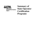
9 For MBR applications, the two configura-tions most often used are hollow fibers grouped in bundles, as shown in Figure 2, or as flat plates. The hollow fiber bundles are connected by manifolds in units that are designed for easy changing and servicing. Figure 2. Hollow-fiber membranes (Image from GE/Zenon) DESIGN CONSIDERATIONS Designers of MBR systems require only basic information about the wastewater characteristics, ( , influent characteristics, effluent require-ments, flow data) to design an MBR system. Depending on effluent requirements, certain supplementary options can be included with the MBR system.
10 For example, chemical addition (at various places in the treatment chain, including: before the primary settling tank; before the sec-ondary settling tank [clarifier]; and before the MBR or final filters) for phosphorus removal can be included in an MBR system if needed to achieve low phosphorus concentrations in the effluent. MBR systems historically have been used for small-scale treatment applications when portions of the treatment system were shut down and the 3 wastewater routed around (or bypassed) during maintenance periods.