Transcription of Merlin Gerin technical guide Medium Voltage - …
1 We do more with Gerin technical guideMedium VoltageMV design guideAMTED300014EN_001_01 Schneider ElectricGamme 0 Design GuideGoal5 Presenting and assisting in the selection of MV equipmentin conformity with design rules used to calculate the dimensions or ratings of an MV proposing simple and clear calculation outlines toguide the designer step by showing actual calculation providing information on units of measure andinternational comparing international summaryThis guide helps you to carry out the calculations required to define and determine equipment dimensions and provides useful information enabling you to design your guide is a catalogueof technical know-howintended for Medium voltageequipment ElectricGammeAMTED300014EN_001_01 Schneider ElectricGammeGeneral contentsMV design guidePresentation5 Metal-enclosed factory-built equipmentVoltageCurrentFrequencySwitchge ar functionsDifferent types of enclosures5689910 Design rules11 Short-circuit powerShort-circuit currentsTransformerSynchronous generatorAsynchronous motorReminderThree phase calculation exampleBusbar calculationThermal withstandElectrodynamic withstandIntransic resonant frequencyBusbar calculation exampleDielectric withstandDielectric strength of the mediumShape of partsDistance between partsProtection indexIP codeIK code111213141415172124272931383839394141 41 Switchgear definition45 Medium Voltage circuit breakerCurrent transformerVoltage transformerDerating45546164 Units of measure67 Basic unitsCommon magnitudes and unitsCorrespondence between Imperial unitsand international system units (SI)676769 Standards71 Quoted standardsIEC-ANSI comparison7172 References 81 Schneider Electric documentation ElectricGamme 0.
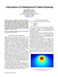
2 AMTED300014EN_001_01 Schneider ElectricGamme 0 Metal-enclosed,factory-built equipmentIntroductionIn order to design a Medium - Voltage cubicle, you need toknow the following basic magnitudes: 5 Voltage5 Current5 Frequency5 Short-circuit Voltage , the rated current and the rated frequency are often known orcan easily be defined, but how can we calculate the short-circuit power orcurrent at a given point in an installation?Knowing the short-circuit power of the network allows us to choose thevarious parts of a switchboard which must withstand significanttemperature rises and electrodynamic constraints. Knowing the Voltage (kV) will allow us to define the dielectric withstand of the : circuit breakers, insulators, , control and protection of electrical networks is achieved by using Metal enclosed switchgear is sub-divided into three types:S metal-cladS compartmented S start with,here is some keyinformation on MV switchboards!reference is made to the InternationalElectrotechnical Commission (IEC).
3 ElectricGamme0 Metal-enclosed,factory-built equipmentVoltageOperating Voltage U (kV)This is applied across the equipment Voltage Ur (kV)Previously known as nominal Voltage , this is the maximum rms. (root mean square) value of the Voltage that the equipment can withstand under normal operating conditions. The rated Voltage is always greater than the operating Voltage and, is associated with an insulation level Ud (kV rms. 1 mn) and Up (kV peak)This defines the dielectric withstand of equipment to switching operationovervoltages and lightning Ud: overvoltages of internal origin, accompany all changes in the circuit: opening or closing a circuit, breakdown or shorting across an insulator, is simulated in a laboratory by the rated power-frequency withstandvoltage for one Up: overvoltages of external origin or atmospheric origin occur whenlightning falls on or near a line. The Voltage wave that results is simulated in a laboratory and is called the rated lightning impulse withstand : IEC 694, article 4 sets the various Voltage values together with, in article 6,the dielectric testing : 5 Operating Voltage : 20 kV5 Rated Voltage : 24 kV5 Power frequency withstand Voltage 50 Hz 1 mn: 50 kV withstand s: 125 kV ElectricGamme0 Metal-enclosed,factory-built equipmentStandardsApart from special cases, Merlin Gerin equipment is in conformity with list 2 of the series 1 table in IEC 60 071 and 60 lightning impulse withstand voltageRated power-frequencywithstand voltageNormal operating s 50 HzkV peak1 minute kV 1list to to to 1524951255020 to to 36 Insulation levels apply to metal-enclosed switchgear at altitudes of less than 1 000 metres, 20 C, 11 g/m3 humidity and a pressure of 1 013 mbar.
4 Above this, derating should be insulation level corresponds to a distance in air which guarantees equipment withstand without a test Voltage kV impulse withstand voltageDistance/earth in air s kV di lectriqueonde de chocUtUm0,5 Um020283850707,21217,52436756095125170 Tensions normalis es CEItension assign eUdUrUptenue di lectrique50 Hz 1 ElectricGamme0 Metal-enclosed, factory-built equipmentCurrentRated normal current: Ir (A)This is the rms. value of current that equipment can withstand when closed, without exceeding the temperature rise allowed in table below gives the temperature rises authorised by the IEC according to the type of normal current:Type of mechanism of materialMax. valuesMax. temperature of conductor ( C)Max. temp. rise = t . max. - 40 Ccontacts in airbare copper or copper alloy7535silver or nickel plated10565tin-plated9050bolted connections or equivalent devicesbare copper, bare copper alloy or aluminium alloy9050silver or nickel : rated currents usually used by Merlin Gerin are:400, 630, 1 250, 2 500 and 3 150 current: I (A)This is calculated from the consumption of the devices connected to the circuit in question.
5 It is the current that really passes through the equipment. If we do not have the information to calculate it, the customer has to provide us with its value. The operating current can be calculated when we know the power of the current :5 For a switchboard with a 630 kW motor feeder and a 1 250 kVA transformer feeder at kV operating the operating current of the transformer feeder:Apparent power:Scalculating the operating current of the motor feeder:cos = power factor = = motor efficiency = 25055/1 732,,--------------------------=130A==I PU3 cos-----------------------------=630---- ---------------------------------------- ---------------82 A== ElectricGamme0 Metal-enclosed, factory-built equipment Minimal short-circuit current: Isc (kA rms.)(see explanation in "Short-circuit currents" chapter.)Rms value of maximal short-circuit current: Ith (kA rms. 1 s or 3 s)(see explanation in "Short-circuit currents" chapter.)Peak value of maximal short-circuit: Idyn (kA peak)(value of the initial peak in the transient period)(see explanation in "Short-circuit currents" chapter.)
6 Frequency fr (Hz)# Two frequencies are usually used throughout the world: S 50 Hz in EuropeS 60 Hz in countries use both frequencies functionsDesignationfunctionCurrent switchingand symboloperatingfaultDisconnecterisolates Earthing disconnecterisolates(short-circuit closing capacity)Switchswitches,does not isolate Disconnecter switchswitchesisolates Fixed circuit breakerswitchesprotectsdoes not isolate Withdrawable circuit breakerswitchesprotectsisolates if withdrawn Fixed contactorswitchesdoes not isolate Withdrawable contactorswitchesisolates if withdrawn Fuseprotectsdoes not isolate (once) = ElectricGamme0 Metal-enclosed, factory-built equipmentDifferent enclosure typesCharacteristicsMetal-cladCompartmen tBlock-typeCubiclesExternal wallsmetal and always earthedNumber of MVcompartments 33 2 Internal partitionsmetal and always earthedindifferentmetalor notindifferentmetalor notPresence of bushings possibleShutters to prevent accessto live compartments Ease of operationswhen live Arcing movement withinthe cubicledifficult, butalways possible = YESP resentation AMTED300014EN_001_01 Schneider ElectricGamme 0 Short-circuit powerWe have to calculate each of the Isc The short-circuit power depends directly on the network configuration and the impedance of its components: lines, cables, transformers, through which the short-circuit current It is the maximum power that the network can provide to an installation during a fault, expressed in MVA or in kA rms for a given operating :operating Voltage (kV)Isc:short-circuit current (kA rms.)
7 Ref: following pagesThe short-circuit power can be assimilated to an apparent The customer generally imposes the value of short-circuit power on us because we rarely have the information required to calculate of the short-circuit power requires analysis of the power flows feeding the short-circuit in the worst possible sources are:5 Network incomer via power Generator Power feedback due to rotary sets (motors, etc); or via MV/LV UIsc =Example 1:25 kA at an operating Voltage of 11 kVExample 2:5 Feedback via LV Isc5 is onlypossible if the transformer (T4) is powered by another source. 5 Three sources are flowing in theswitchboard (T1-A-T2)Scircuit breaker D1 (s/c at A)Isc1 + Isc2 + Isc3 + Isc4 + Isc5 Scircuit breaker D2 (c/c at B)Isc1 + Isc2 + Isc3 + Isc4 + Isc5 Scircuit breaker D3 (c/c at C)Isc1 + Isc2 + Isc3 + Isc4 + Isc563 kVT1AT2 ABCD1D6 MTBTD4D5D7D2D310 kVT3 MBTMTT4 Icc4 Icc5 Icc1 Icc2 Icc3 Design ElectricGamme0 Short-circuit currentsfigure 15 In order to choose the right switchgear (circuit breakers or fuses) andset the protection functions, three short-circuit values must be known:S minimal short-circuit current: (example: 25 kA rms)This corresponds to a short-circuit at one end of the protected link (fault at the end of a feeder (see )) and not just behind the breaking mechanism.
8 Its value allows us to choose the setting of thresholds for overcurrent protection devices and fuses; especially when the length of cables is high and/or when the source is relatively impedant (generator, UPS).S rms value of maximal short-circuit current:(example: 25 kA rms. 1 s)This corresponds to a short-circuit in the immediate vicinity of the upstream terminals of the switching device (see ). It is defined in kA for 1 or 3 second(s) and is used to define the thermal withstand of the peak value of the maximum short-circuit current:(value of the initial peak in the transient period)( 25 kA = kA peak IEC 60 056 25 kA = kA peak ANSI )- Idyn is equal Isc at 50 Hz (IEC) or, Isc at 60 Hz (IEC) or, Isc (ANSI) times the short-circuit currentcalculated at a given point in the determines the breaking capacity and closing capacity of circuit breakers and switches, as well as the electrodynamic withstand of busbars and The IEC uses the following values: 8 - - 16 - 20 - 25 - - 40 kA rms.
9 These are generally used in the :#A specification may give one value in kA rms and one value in MVA as below:Isc = 19 kA rms or 350 MVA at 10 kV5if we calculate the equivalent current at 350 MVA we find:The difference lies in the way in which we round up the value and in local value 19 kA rms is probably the most explanation is possible: in Medium and high Voltage , IEC 909 applies a coefficient of when calculating maximal Isc.(Cf: example 1, p 12 Introduction).This coefficient of takes account of a Voltage drop of 10 % across the faulty installation (cables, etc).All electrical installations have to be protected against short-circuits, without exception, whenever there is an electrical discontinuity; which more generally corresponds to a change in conductor cross-section. The short-circuit current must be calculated at each stage in the installation for the various configurations that are possible within the network; this is in order to determine the characteristics that the equipment has to have withstand or break this fault ble MTI cr te = IdynCourantComposante continueTempsIsc = (kA rms)Ith = (kA rms.)
10 1 s or 3 s)Idyn = (kA peak)Isc3503 kA rms==Isc11/U3/Zcc----------------------, EZcc--------==Design rulesAMTED300014EN_001_01 Schneider ElectricGamme0 Short-circuit currentsDesign rulesTransformerIn order to determine the short-circuit current across the terminals of a transformer, we need to know the short-circuit Voltage (Usc %).5 Usc % is defined in the following way: the Voltage transformer is not powered: U = 0 place the secondary in short-circuit gradually increase Voltage U at the primary up to the rated current Ir in the transformer secondary short-circuit current, expressed in kA, is given by the following equation:The short-circuit current depends onthe type of equipment installed onthe network (transformers,generators, motors, lines, etc).Example:5 Transformer 20 MVA5 Voltage 10 kV5 Usc = 10 %5 Upstream power: infiniteIrSr3 U no-load-------------------------------20 0003/10------------------ 1 150 A===IscIrUsc---------=1 15010100 ---------------------=11 500 kA==A I : O Ir U : O Uccpotentiom treprimairesecondaireV123 The value U read across the primary is then equal to UscIscIrUsc---------= ElectricGammeDesign rules0 Short-circuit currents1 Synchronous generators(alternators and motors)Calculating the short-circuit current across the terminals of a synchronous generator is very complicated because the internal impedance of the latter varies according to When the power gradually increases, the current reduces passing through three characteristic periods.