Transcription of METAL STAMPING DESIGN GUIDE - Thomasnet
1 Basic DESIGN concepts that improve quality and cut costsMETAL STAMPINGDESIGN GUIDE452 Twin Lakes Rd North Branford, CT Phone: 800-486-5546 Fax: 800-486-2825 2 IntroductionMetal STAMPING is a complex process that can include a number of METAL forming processes blanking, punching, bending, and piercing, to name a of these processes come with fundamentals that, when followed, allow manufacturers to produce the highest quality components for the lowest costs. It s also critical to understand these fundamentals so you can: Avoid costly errors Know what to expect in terms of costs and lead times Receive the highest quality components so your application performs at its bestThe following GUIDE illustrates best practices and formulas commonly employed in the METAL STAMPING DESIGN process and includes tips to incorporate cost cutting considerations into your Twin Lakes Rd North Branford, CT Phone: 800-486-5546 Fax: 800-486-2825 3 BlankingBlanking cutting the rough, basic shape is often the first step for a stamped METAL part.
2 The primary concerns at the blanking stage of the DESIGN are minimizing and avoiding burrs, which require secondary processing to remove and can drive up the cost of your part and extend lead is a common METAL STAMPING process and ideal for forming holes and slots fully enclosed within the edges of a part. There are a number of factors to consider when designing stamped METAL parts with holes to ensure proper manufacturing and DiameterThe minimum diameter of any hole should be the material thickness or larger. Holes in materials with high tensile strength, such as stainless steel alloys, should be at least 2x wider than the material is with smaller diameters require specialized punching or drilling processes, which themselves often require deburring.
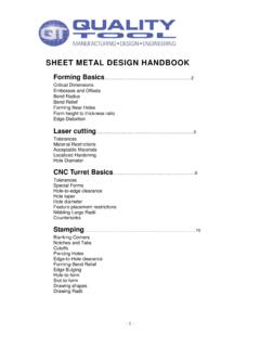
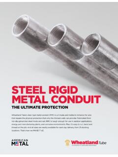
3 Specialized processes add to the cost of your Geometry/Taper When a hole is punched in the STAMPING process it does not have a constant profile through the entire thickness of the part. The section view of a punched hole is shown below. The taper in the bottom side of the hole is caused by the punched hole diameter breaking through the material. The amount of taper in a punched hole is relative to the die clearance between the punch and the die used to punch the hole geometry. If a constant diameter is needed through the entire material thickness, a part must be drilled or machined as a secondary operation, resulting in much higher piece = HOLEMACHINED HOLE452 Twin Lakes Rd North Branford, CT Phone: 800-486-5546 Fax: 800-486-2825 4 Edge-to-Hole SpacingThe web the space between a hole and the edge of a part should be at least twice the distance as the material is thick.
4 If edge-to-hole spacing is less than this distance, bulging along the edge will occur. If holes are required nearer to the edge than twice the material thickness, and bulge must be avoided, specialty drilling processes will be oblong slots that are less than 10 material thicknesses long, edge-to- hole spacing should be 2x material thickness; oblong slots longer than 10 material thicknesses require edge-to-hole spacing of at least 4x the material thickness to avoid STAMPING is a linear process wherein one step is performed after another, after another, and so on until a completed part is produced. The best stamped METAL part designs take this step-by-step nature of the STAMPING process into of the more substantial forms, often performed toward the end of the progressive die STAMPING process, is bending.
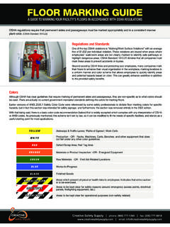
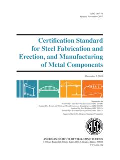
5 When designing bends into your stamped METAL part, it is important to allow for enough material make sure to DESIGN your part and its blank so that there is enough material to perform the Bends Near HolesWhen a bend is made too close to a hole, the hole becomes deformed. For holes or slots less than in diameter or width, the minimum distance between a hole and the bend should be 2x the material thickness, plus the radius of the holes greater than in diameter, the minimum distance should be the material thickness plus the radius of the = + RD = + RD = 2T + RD = 2T + R452 Twin Lakes Rd North Branford, CT Phone: 800-486-5546 Fax: 800-486-2825 5 Allowing less space than these standards will result in the hole distorting, bulging or stretching outside of its tolerances.
6 Holes that must be closer to a form may require a post- STAMPING drilling processes, which can be very and TabsNotches and tabs, as well as slots, should be designed with widths that are at least the thickness of the material. If made any smaller, they can be difficult to create due to the force exerted on punches, causing them to break. In certain DESIGN situations, high precision stampers can accommodate smaller measurements, but be sure that they are absolutely corner in your blank DESIGN should have a radius that is at least half of the material thickness. If your material is or less in thickness, corners can be very sharp. BurrsBurr allowance is generally 10% of the thickness of the sheet material. To minimize instances and severity of burrs, avoid sharp corners and complex cutouts when possible.
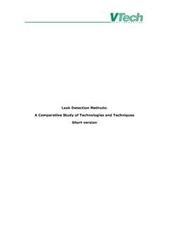
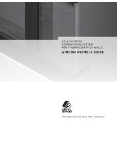
7 When such factors cannot be avoided, be sure to note burr direction in your DESIGN so they can be taken into account during STAMPING (See the Stamped Edges image below). Vibratory and tumble finishing can be performed to remove burrs when EdgesWhen METAL is cut or sheared, the applied downward stress on the material causes it to fracture as soon as the METAL s shear strength the maximum strength a material withstands before separating at the cut location is met. This action creates a burr on the bottom edge of the material, as shown in the diagram. This STAMPING burr from the cutting process is critical for product designers to understand, as it creates an angle which can cause dimensional measurements to differ as compared to measuring from the burnished area.
8 While this difference is very slight, it can come into play when parts are being held to very tight tolerances. The height of the burr, the fracture angle, and the depth of the fracture can vary depending on material type, punch to die clearance and tool heightFracture depthBurnish depthRollover depthPenetration depthNOTCHTABMIN. W = RADIUS R = .5 TRRTRPENETRATION DEPTHROLLOVER DEPTHBURNISH DEPTHFRACTURE DEPTHBURR DEPTHFRACTURE ANGLERR452 Twin Lakes Rd North Branford, CT Phone: 800-486-5546 Fax: 800-486-2825 6 CoiningCoining the edges of a part is sometimes an option when trying to avoid costly secondary processes like vibratory deburring or edge grinding. During the coining process, edges of a stamped METAL part are struck in such a manner as to flatten or break the burr; this can create a much smoother edge in the coined area of the part geometry.
9 In addition to providing cost savings from secondary processes, coining can also add additional strength to localized areas of the and Grain DirectionPlasticity is the measure of permanent deformation a material undergoes when subjected to more plasticity a METAL has, the easier it is to form. High plasticity metals such as aluminum, brass, copper, and mild varieties of steel are formed easily and may require fewer considerations in regards to bends. The grain direction of these metals is not a major concern, and they generally require an inside bend height minimum of 20% less than higher strength metals (See bend height section below). When bending high strength materials tempered metals, stainless steels, and so on grain direction becomes very important.
10 Bends that go along the grain of a high strength METAL are prone to cracking, which will make your part susceptible to failure. Thus, it becomes important to DESIGN bends in high strength material parts against the grain of the Height When adding a bend or form to a stamped METAL part, the height of the bend becomes a DESIGN consideration. The thickness of the material comes into play when considering the overall height of the bend from the base material. The overall height of a bend has minimum requirements to be formed effectively and should be at minimum, the thickness of the material + the radius of the bend. At times, the height of a bend may be less than +R but can require costly secondary Relief When a bend is made too close to an edge, the material on the base of the part along either side of the bent section may tear, drastically reducing the integrity of your part.