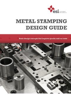
Transcription of SHEET METAL DESIGN HANDBOOK
1 - 1 - SHEET METAL DESIGN HANDBOOK Forming 2 Critical Dimensions Embosses and Offsets Bend Radius Bend Relief Forming Near Holes Form height to thickness ratio Edge Distortion Laser Tolerances Material Restrictions Acceptable Materials Localized Hardening Hole Diameter CNC Turret Tolerances Special Forms Hole-to-edge clearance Hole taper Hole diameter Feature placement restrictions Nibbling Large Radii Countersinks Blanking-Corners Notches and Tabs Cutoffs Piercing Holes Edge-to-Hole clearance Forming-Bend Relief Edge Bulging Hole-to-form Slot-to-form Drawing shapes Drawing Radii - 2 - Forming Basics Press brake forming-The fundamental advantage of a press brake as a forming tool is its flexibility.
2 By using standard vee-dies, cost savings can be realized through economical set-ups and run times on small lots and prototypes. In addition to these considerations, using the following guidelines will increase the manufacturability of designs for press brake forming. Dimension the part in a single direction wherever possible. Because of the sequential nature of the forming process, and the fact that dimensional variation is introduced at each bend, dimensioning in a single direction parallels the process and helps to control tolerance accumulation.
3 Furthermore, allow a more generous bend tolerance (+/- .007 ) as tighter tolerances, while achievable, will result in higher costs. Use consistent bend radius for all bends per part, when possible it helps minimize setup changes. Additionally, we prefer radii specs in fractions of an inch, as our tooling is sized accordingly. Generally, dimensioning should be done from a feature to an edge. Avoid feature-to-feature dimensions over two or more planes. Feature-to-bend dimensions may require special fixtures or gauging. This also means that tolerances in the title block of a drawing may be unnecessarily restrictive for certain dimensions and angles, while very appropriate for others.
4 Critical Dimensions SHEET METAL Forming Outside dimension should be used unless the inside dimension is critical. - 3 - Embosses and Offsets Emboss and offset dimensions should be to the same side of the material unless the overall height is critical. Only the truly critical dimensions should be highlighted as such. Placing excessively high tolerances and redundant critical dimensions can dramatically increase the cost of the part. Bend Radius- As a rule, inside bend radius should be equal to material thickness. When the radius is less than recommended, this can cause material flow problems in soft material and fracturing in hard material.
5 Bend Relief - When a bend is made close to an edge the material may tear unless bend relief is given. Figure "A" shows a torn part. Figure "B" shows a part with the edge a sufficient distance from the form. This distance should never be less than the radius of the bend. Figure "C" shows a bend relief cut into the part, again the depth of the relief should be greater than the radius of the bend. The width of the relief should be a material thickness or greater, preferably a material thickness + 1/64". - 4 - Forming Near Holes When a bend is made too close to a hole, the hole may become deformed.
6 Figure "A" shows a hole that has become teardrop shaped because of this problem. To save the cost of punching or drilling in a secondary operation the following formulas can be used to calculate the minimum distance required: For a hole < 1" in diameter the minimum distance "D" = 2T + R (see fig. "B") For a slot or hole > 1" diameter then the minimum distance "D" = + R (see fig. "C") Form height to thickness ratio To determine the minimum form height for SHEET METAL use the following formula: D = + R (see below) The height can be less but it required secondary operations and is far more costly.
7 - 5 - Edge Distortion An exaggerated example of edge deformation is pictured in figure "A" below. The overhang caused by this distortion can be as large as the material thickness. As material thickness increases and bend radius decreases the overhang becomes more severe. In situations where an overhang is unacceptable the part can be relieved as in figure "B". Laser Cutting Basics With very little set up time, no tooling and the advent of CAD to CAM production, lasers are often utilized in prototyping and production parts.
8 Well suited for intricate details and irregular contours, additional economies can be obtained through the nesting of parts when laser cutting. Tolerances The feature to feature tolerance on for the laser cutter is + " but is typically held much closer. The smallest cut possible is dictated by the width of the beam or .008" wide. Material restrictions Materials have three factors that restrict them from laser cutting. These factors are reflectivity, thickness and flammability. Reflectivity causes a problem because the cutting beam gets scattered.
9 Material that is too thick has the same problem: molten METAL scatters the beam before the part is fully cut. We can cut METAL as thick as 3/8" but the edge quality suffers greatly. The degree of material flammability is another important factor. Some parts considered flammable can be used. It is best to test flammable or heat sensitive materials before releasing a production part. Below is a list of some of the material we have used. Acceptable Materials Any raw steel (Stainless, CRS, HRS) Aluminum Some deburring issues Plastic Check heat & flammability Cardstock Check heat & flammability Galvanized, Galvaneal Unacceptable Materials Copper Highly reflective - 6 - Paper stock Unless treated with flame retardant Silver & other prec.
10 Metals Highly Reflective Localized Hardening Due to the intense heat associated with laser cutting, the edges of the material can become hardened. This area is referred to as the Heat Affected Zone (HAZ). This is especially important for secondary operations such as reaming and tapping. The HAZ increases in thicker materials. Hole diameter The entry diameter is larger than the exit diameter, creating a slightly tapered hole. Minimum hole sizes are related to stock thicknesses and can be as low as 20% of the stock thickness. Turret Press Basics CNC Turret presses are particularly suited for low to medium quantity production runs.
