Transcription of Metering Data - Electrical Sector
1 Metering data data subject to change without notice. Consult local utility for area acceptance. All dimensions are in inches. Metering Data126 Meter Mounting EquipmentEnergization of Electrical EquipmentBefore energizing1) Give equipment a thorough visual examination to determine that: A) Proper clearances have been maintained B) All connections have been made C) Equipment is clean and dry2) Make a thorough physical examination to verify: A) Tightness of all bolted connections see table B) Manually operate all circuit breakers, switches, relays, etc.
2 C) Check rigidity of all mountings, bus bars and components3) All switches and circuit breakers should be in the off position4) Mount covers and close doors*Use 80-in-lbs. when threaded in aluminum bus Torque RequirementsScrew Type Screw Size Torque Tolerances #10-32 30 5 or Phillips #12-24 38 5 1/4 -20 45 5 5/16 -18 60 5 1/4 -20 72 10 5/16 -18 85 10 Head 3/8 -16
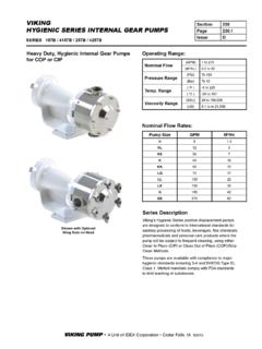
3 175 15 7/16 -14 399 20 1/2 -13 375 25 Potential Wiring of 13, 14, & 15 Jaw SocketsFront ViewMetering data data subject to change without notice. Consult local utility for area acceptance. All dimensions are in inches. Metering DataMeter Mounting Equipment127 Location of Socket Jaws4-TerminalForm 1S & 2S5-TerminalForm 3S7-TerminalForm 14S, 15S, 16S, 17S, 24S8-TerminalForm 5S, 35S, 45S15-TerminalForm 11S, 39S, 76S13-TerminalForm 6S, 8S, 9S,10S, 29S, 36S, 46S6-TerminalForm 4 SMetering data data subject to change without notice.
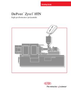
4 Consult local utility for area acceptance. All dimensions are in inches. Metering Data128 Meter Mounting EquipmentWith Safety Test By-Pass BlocksCurrent Transformer Installations3 - 4 Wire Y or 3 Wire, 1-2-3 or Network2 ElementMeterMeterDisconnectLineNLineLoad LineN or 2 LoadLineN or 2 LoadBondable NeutralBondable NeutralLoad2 or 3 ElementMeter3 Wire Using CT s 2 or 3 Element Meter3 Wire Using CT sBypass For Use WithJumper LinksWiring DiagramsMetering data data subject to change without notice. Consult local utility for area acceptance.
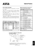
5 All dimensions are in inches. Metering DataMeter Mounting Equipment129 Current Transformer Installations3 - 4 Wire Y or Using CT s2 or 3 Element Meter3 - 4 Wire Y Using CT s2 or 3 Element Meter3 - 4 Wire Using CT s3 Element Meter3 - 4 Wire Using CT s2 Element MeterLineLine2N312N31 LoadLoadLineLine2N312N31 LoadLoadWiring DiagramsMetering data data subject to change without notice. Consult local utility for area acceptance. All dimensions are in inches. Metering Data130 Meter Mounting EquipmentEnergization of Electrical EquipmentaThe cross section may be reduced to percent of the total cross section of the largest main service conductor(s) of the samematerial (copper or aluminum)
6 For any phase on equipment rated 1200 amperes and equipment rated 1200 amperes or more and that has wiring terminals intended to connect service conductor wires sized largerthan 600 kcmil copper or 750 kcmil aluminum, the cross section of the main bonding jumper shall be at least percent of the thetotal cross section of the largest main service entrance conductor(s) of the same material (copper or aluminum) for any Equivalents:dA No. 8 ( mm diameter) or larger brass or No. 10 ( diameter) or larger steel screw may be No. 10 or larger brass or steel screw may be No. 10 or larger brass screw may be 1/4inch ( ) diameter or larger brass or steel screw may be the ampere rating is 400 and the wire terminal connectors for the main service conductors are rated for two No.
7 3/0 AWGcopper or two No. 250 kcmil aluminum conductor, but will not accept a 600 kcmil conductor, these values may be reduced to No. 2 AWG ( square inch) copper or No. 0 AWG ( square inch) Jumper Cross Section of Main Bonding Size of Main BondingJumper Jumper in Square Inches Grounded Service Conductor Ampere Rating (Minimum) a,b,c (Minimum) a,b,c (Minimum) Not Exceeding Copper Aluminum Copper Aluminum Copper Aluminum 90 8 6 8 6 100 6 4 6 4 125 6 4 6 4 150
8 6 4 6 4 200 4 2 4 4 300 2 1/0 ,g ,g 4 1/0 400 1/0h 3/0h ,h ,h 1/0 3/0h 500 0 3/0 1/0 3/0 600 2/0 4/0 2/0 4/0 800 2/0 4/0 2/0 4/0 1000 3/0 250 kcmil
9 3/0 250 kcmil 1200 250 kcmil 300 kcmil 250 kcmil 250 kcmil 1600 300 kcmil 400 kcmil 300 kcmil 400 kcmil 2000 400 kcmil 500 kcmil 400 kcmil 500 kcmil Min. Cross Section Wire Size Min. Cross SectionWire Size, AWG (MM2) (MM2)
10 8 4/0 107 6 250 kcmil 126 4 200 kcmil 152 2 400 kcmil 203 1/0 500 kcmil 253 2/0 600 kcmil 304 3/0 750 kcmil 380 Metering data data subject to change without notice.