Transcription of METHOD 27 - DETERMINATION OF VAPOR …
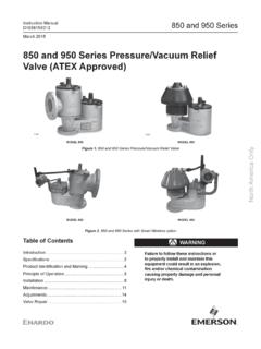
1 1390 METHOD 27 - DETERMINATION OF VAPORTIGHTNESS OF gasoline delivery TANKUSING pressure vacuum Scope and Applicability. This METHOD is applicable for thedetermination of VAPOR tightness of a gasoline delivery tankwhich is equipped with VAPOR collection Summary of METHOD . pressure and vacuum are applied alternately tothe compartments of a gasoline delivery tank and the changein pressure or vacuum is recorded after a specified periodof Allowable pressure change ()p) means theallowable amount of decrease in pressure during the staticpressure test, within the time period t, as specified in theappropriate regulation, in mm Allowable vacuum change ()v) means the allowableamount of decrease in vacuum during the static vacuum test,within the time period t, as specified in the appropriateregulation, in mm Compartment means a liquid-tight division of adelivery delivery tank means a container, includingassociated pipes and fittings, that is attached to or forms1391a part of any truck, trailer, or railcar used for thetransport of delivery tank VAPOR collection equipment meansany piping, hoses, and devices on the delivery tank used tocollect and route gasoline vapors either from the tank to abulk terminal VAPOR control system or from a bulk plant orservice station into the gasoline means a petroleum distillate orpetroleum distillate/alcohol blend having a Reid vaporpressure of kilopascals or greater which is used as afuel for internal combustion Initial pressure (Pi)
2 Means the pressure appliedto the delivery tank at the beginning of the static pressuretest, as specified in the appropriate regulation, in mm Initial vacuum (Vi) means the vacuum applied tothe delivery tank at the beginning of the static vacuumtest, as specified in the appropriate regulation, in mm Time period of the pressure or vacuum test (t)means the time period of the test, as specified in theappropriate regulation, during which the change in pressureor vacuum is monitored, in Interferences. [Reserved] Safety. gasoline contains several volatile organiccompounds ( benzene and hexane) which presents apotential for fire and/or explosions. It is advisable totake appropriate precautions when testing a gasolinevessel's VAPOR tightness , such as refraining from smokingand using explosion-proof This METHOD may involve hazardous materials,operations, and equipment. This test METHOD my not addressall of the safety problems associated with its use.
3 It isthe responsibility of the user of this test METHOD toestablish appropriate safety and health practices anddetermine the applicability of regulatory limitations priorto performing this test Equipment and Supplies. The following equipment and supplies are required pressure Source. Pump or compressed gas cylinderof air or inert gas sufficient to pressurize the deliverytank to 500 mm (20 in.) H2O above atmospheric Regulator. Low pressure regulator forcontrolling pressurization of the delivery vacuum Source. vacuum pump capable of evacuatingthe delivery tank to 250 mm (10 in.) H2O below pressure - vacuum Supply Manometer. Liquid manometer, or equivalentinstrument, capable of measuring up to 500 mm (20 in.) H2 Ogauge pressure with mm ( in.) H2O pressure - vacuum Relief Valves. The testapparatus shall be equipped with an inline pressure -vacuumrelief valve set to activate at 675 mm ( in.)
4 H2O aboveatmospheric pressure or 250 mm (10 in.) H2O belowatmospheric pressure , with a capacity equal to thepressurizing or evacuating Test Cap for VAPOR Recovery Hose. This cap shallhave a tap for manometer connection and a fitting with shut-off valve for connection to the pressure - vacuum supply Caps for Liquid delivery Reagents and Standards. [Reserved] Sample Collection, Preservation, Storage, Pretest Summary. Testing problems may occur due to thepresence of volatile vapors and/or temperature fluctuationsinside the delivery tank. Under these conditions, it isoften difficult to obtain a stable initial pressure at thebeginning of a test, and erroneous test results may occur. To help prevent this, it is recommended that prior to1394testing, volatile vapors be removed from the tank and thetemperature inside the tank be allowed to stabilize. Because it is not always possible to completely attain thesepretest conditions, a provision to ensure reproducibleresults is included.
5 The difference in results for twoconsecutive runs must meet the criteria in Sections Emptying of Tank. The delivery tank shall beemptied of all Purging of VAPOR . As much as possible thedelivery tank shall be purged of all volatile vapors by anysafe, acceptable METHOD . One METHOD is to carry a load ofnon-volatile liquid fuel, such as diesel or heating oil,immediately prior to the test, thus flushing out all thevolatile gasoline vapors. A second METHOD is to remove thevolatile vapors by blowing ambient air into each tankcompartment for at least 20 minutes. This second METHOD isusually not as effective and often causes stabilizationproblems, requiring a much longer time for stabilizationduring the Temperature Stabilization. As much aspossible, the test shall be conducted under isothermalconditions. The temperature of the delivery tank should beallowed to equilibrate in the test environment.
6 During thetest, the tank should be protected from extreme1395environmental and temperature variability, such as directsunlight. Test Open and close each dome Connect static electrical ground connectionsto the tank. Attach the liquid delivery and VAPOR returnhoses, remove the liquid delivery elbows, and plug theliquid delivery : The purpose of testing the liquid deliveryhoses is to detect tears or holes that would allow liquidleakage during a delivery . Liquid delivery hoses are notconsidered to be possible sources of VAPOR leakage, andthus, do not have to be attached for a VAPOR leakage test. Instead, a liquid delivery hose could be either visuallyinspected, or filled with water to detect any Attach the test cap to the end of the vaporrecovery Connect the pressure - vacuum supply hose andthe pressure - vacuum relief valve to the shut-off valve. Attach a manometer to the pressure Connect compartments of the tank internallyto each other if possible.
7 If not possible, each1396compartment must be tested separately, as if it were anindividual delivery pressure Connect the pressure source to the pressure - vacuum supply Open the shut-off valve in the VAPOR recoveryhose cap. Apply air pressure slowly, pressurize the tank toPi, the initial pressure specified in the Close the shut-off and allow the pressure inthe tank to stabilize, adjusting the pressure if necessaryto maintain pressure of Pi. When the pressure stabilizes,record the time and initial At the end of the time period (t) specifiedin the regulation, record the time and final Repeat steps through untilthe change in pressure for two consecutive runs agreeswithin mm ( in.) H2O. Calculate the arithmeticaverage of the two Compare the average measured change inpressure to the allowable pressure change, )p, specified inthe regulation. If the delivery tank does not satisfy thevapor tightness criterion specified in the regulation,repair the sources of leakage, and repeat the pressure testuntil the criterion is met.
8 Disconnect the pressure source from thepressure- vacuum supply hose, and slowly open the shut-offvalve to bring the tank to atmospheric vacuum Connect the vacuum source to the pressure - vacuum supply Open the shut-off valve in the VAPOR recoveryhose cap. Slowly evacuate the tank to Vi, the initialvacuum specified in the Close the shut-off valve and allow thepressure in the tank to stabilize, adjusting the pressure ifnecessary to maintain a vacuum of Vi. When the pressurestabilizes, record the time and initial At the end of the time period specified inthe regulation (t), record the time and final Repeat steps through untilthe change in vacuum for two consecutive runs agrees within mm ( in.) H2O. Calculate the arithmetic average ofthe two Compare the average measured change in vacuumto the allowable vacuum change, )v, as specified in theregulation. If the delivery tank does not satisfy the vaportightness criterion specified in the regulation, repair thesources of leakage, and repeat the vacuum test until thecriterion is Disconnect the vacuum source from thepressure- vacuum supply hose, and slowly open the shut-offvalve to bring the tank to atmospheric Post-Test Clean-up.
9 Disconnect all testequipment and return the delivery tank to its Quality (s)Quality Control test proceduresuntil change inpressure or vacuum fortwo consecutive runsagrees within mm( in.) H2 OEnsures Calibration and Standardization. [Reserved] Analytical Procedures. [Reserved] Data Analysis and Calculations. [Reserved] METHOD Precision. The VAPOR tightness of a gasolinedelivery tank under positive or negative pressure , asmeasured by this METHOD , is precise within mm ( in.) Bias. No bias has been Pollution Prevention. [Reserved] Waste Management. [Reserved] Alternative The pumping of water into the bottom of adelivery tank is an acceptable alternative to the pressuresource described above. Likewise, the draining of water outof the bottom of a delivery tank may be substituted for thevacuum source. Note that some of the specific step-by-step1400procedures in the METHOD must be altered slightly toaccommodate these different pressure and vacuum Techniques other than specified above may beused for purging and pressurizing a delivery tank, if priorapproval is obtained from the Administrator.
10 Such approvalwill be based upon demonstrated equivalency with the References. [Reserved] Tables, Diagrams, Flowcharts, and Validation Data. [Reserv]