Transcription of METHOD OF MEASURING SHUNT RESISTANCE IN …
1 Measurement Science Conference 2001, Anaheim, CA January 2001 METHOD OF MEASURING SHUNT RESISTANCE IN PHOTODIODES Paul R. Thompson1 and Thomas C. Larason2 1 Rochester Institute of Technology Summer Student Guest Researcher at the National Institute of standards and Technology Gaithersburg, MD 20899-8441 2 National Institute of standards and Technology 100 Bureau Drive, Stop 8441 Gaithersburg, MD 20899-8441 301-975-2334 Abstract - A METHOD of MEASURING the SHUNT RESISTANCE of diodes, specifically photodiodes, is examined and the procedure of how the METHOD is implemented using LabVIEW is detailed.
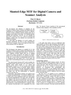
2 Rudimentary comparison with other accepted methods in industry is done. The uncertainty analysis of the measurements using the specified METHOD is given. Introduction A photodiode has two RESISTANCE components in the equivalent circuit [1] shown in Fig. 1, the series and SHUNT RESISTANCE . LOADILCjRshRsRLIOVOIL : Current generated by the incident lightCj : Junction CapacitanceRsh : SHUNT resistanceRs : Series resistanceRL : Load resistanceIO : Output currentVO : Output voltage Fig. 1: photodiode equivalent circuit. The series resistor is in series with the photocurrent source, and the SHUNT resistor is in parallel with the photocurrent source.
3 In instruments using photodiodes (or any other diode for that matter), it is important to know the value of the SHUNT RESISTANCE , so an appropriate load can be placed across the terminals of the photodiode such that a significant percentage of the generated photocurrent reaches the load. The SHUNT RESISTANCE is defined to be the inverse slope of the I-V curve at the 0 V point. To make the curve consistent with the theoretical model, the light input must be constant. Calculating the slope of the curve at the 0 V point is time-intensive, so the generally accepted practice in the industry is to measure the current I at V = 10 mV, and apply Ohm s law to find the SHUNT RESISTANCE Rsh.
4 DIdVR=sh (1) Measurement Science Conference 2001, Anaheim, CA January 2001 Knowing the value of the SHUNT RESISTANCE is important because of the nature of electronic current to flow in the path of least RESISTANCE . In highly sensitive measurements, where large resistors are used in the feedback of an operational amplifier, it is essential to have high SHUNT RESISTANCE so that very small photocurrents can be measured. At the same time with high current gains, low voltage gains can be achieved if the SHUNT RESISTANCE is large.
5 In addition, for applications such as trap detectors [2], which employ several photodiodes connected in parallel, the resultant noise performance of the trap detector is improved if the photodetectors have similar SHUNT resistances. This paper will propose a METHOD to easily calculate the slope of the line at the 0 V point, and compare it to the results derived from the 10 mV METHOD and compare the uncertainties. Procedure The instrument used to measure and plot the I-V curve of the photodiodes was a HP 4145A Semiconductor Parameter Analyzer [3] connected to a PC via a GPIB cable.
6 LabVIEW was used to communicate with the HP 4145A. A program was written to set software parameters for the I-V curve measurements and to download the data of the measurements. The data from the measurements were then analyzed mathematically; details of which will be provided later in the paper. The photodiode in question was clipped to the leads of the probe, and placed in a HP 16058A test fixture, which blocked light and electromagnetic interference. Previously, the SHUNT RESISTANCE of the photodiode was determined by fitting a line tangent to the 0 V point of the curve by eye using a line-positioning feature of the HP 4145A, and reading the inverse of the slope off the display of the 4145A.
7 Numerically fitting a certain portion of the curve around the 0 V area with a least-squares linear fit can do this. That eliminates a significant portion of uncertainty stemming from operator placement of the tangent line. The linear fit METHOD was chosen rather than numerically deriving the slope from the 0 V point because numerical derivations are sensitive to fluctuations in the curve. Owing to the experimental nature of the data, significant fluctuations were present, enough to introduce large errors if numerical derivation was used. Some of the photodiodes exhibited jagged curves, probably resulting from electromagnetic interference.
8 For those curves, a fourth-order polynomial was fitted to the experimental data, and the slope was obtained from the result. A 4th order polynomial was chosen to allow enough flexibility to match the shape of the curve, but not so much that the curve fit follows the deviations. In fitting the straight line, two considerations need to be addressed. The data set for the linear fit needs to contain enough points so that the influence of the fluctuations of the experimental data from the theoretical line is minimized in the linear fit. The domain of the set should not be so large that the fitted line resembles more of a chord of a circle than the tangent.
9 It was arbitrarily decided that the set for the linear fit should range from -4 mV to 4 mV and encompass eight data points. The +10 mV and -10 mV measurements were performed by locating the current that corresponds to the 10 mV points, respectively, and applying Ohm s law to obtain the RESISTANCE . Data/Observations Initially, when the SHUNT RESISTANCE of a silicon photodiode was measured without pause between measurements, it was noticed that the RESISTANCE steadily increased. An example of this is shown in Fig. 2. Measurement Science Conference 2001, Anaheim, CA January 2001 255260265270275280285024681012 Measurement # SHUNT RESISTANCE (Mohm) Fig.
10 2: Comparison between measurements done in succession and measurements spaced by five minutes. The top line indicates data that was measured in succession. The bottom line is data that was measured in intervals of five minutes. Apparently, the effect occurs because as the current flows through the photodiode , the temperature of the photodiode increases. The SHUNT RESISTANCE is strongly temperature-dependent [4, 5]. Spacing the measurements by an arbitrarily chosen time of approximately five minutes eliminated this effect. A Fluke 52 thermocouple was used in an attempt to judge the effect of temperature on the SHUNT RESISTANCE values, but the resolution of the thermocouple was greater than the magnitude of the temperature change of the photodiode , so the contribution of temperature variation to the uncertainty is unknown.