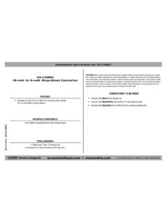
Transcription of metraonline.com
1 CAUTION! All accessories, switches, climate controls panels, and especially air bag indicator lights must be connected before cycling the ignition. Also, do not remove the factory radio with the key in the on position, or while the vehicle is running. The World s best kits. COPYRIGHT 2018 METRA ELECTRONICS CORPORATION REV. 8/28/18 INST99-5838 CHINSTALLATION INSTRUCTIONS99-5838 CHKIT FEATURES ISO DIN radio provision with pocket ISO DDIN radio provision Painted charcoal Touchscreen display for climate and personalization featuresKIT COMPONENTS A) Radio trim panel with touchscreen display B) Radio brackets C) SYNC module brackets D) Pocket E) Engine start/stop circuit board and cover F) Engine start/stop trim G) (4) #8 x 3/4 Phillips pan-head screws H) (4) #8 x 3/8 Phillips truss-head screws I) (6) #4 x 1/2 Phillips pan-head screws J) (4) Panel clips K) USB cable L) HVAC interface and wiring harness (not shown) M) Antenna adapter (not shown)
2 TOOLS REQUIRED Panel removal tool Phillips screwdriver 9/32 socket wrench Cutting tool Torx T-10 screwdriverTABLE OF CONTENTSDash Disassembly ..2-4 Kit Preparation ..5-7 Kit Assembly ISO DIN radio provision with pocket ..8 ISO DDIN radio provision ..8 Axxess Interface installation ..9-17 WIRING & ANTENNA CONNECTIONSW iring Harness: Axxess interface & harness includedAntenna Adapter: IncludedFord Mustang (with screen) 2015-2017 | Open the passenger door and remove the trim panel from the side of the dash. (Figure A)2. Open the glove box and remove the trim panel on the right side. (Figure B)3. Unclip and remove the trim/vent dash panel. (Figure C) Continued on the next page(Figure B)(Figure A)(Figure C)DASH DISASSEMBLY2 REV.
3 8/28/2018 INST99-5838 CHDASH DISASSEMBLY (CONT.)3(Figure F)(Figure D)(Figure E)4. Remove the rubber tray cover in front of the shifter, and then remove the (2) 9/32 screws exposed. (Figure D)5. Unclip and remove the front side panels from each side of the center console. (Figure E)6. Remove the (2) 9/32 screws from each side of the center console. (Figure F) Continued on the next | DISASSEMBLY (CONT.)(Figure I)(Figure H)(Figure J)(Figure G)7. Unclip the shifter trim bezel and slightly pull it up to clear the center console Open the center console storage compartment, unclip the top of the console, and then slide it toward the rear of the vehicle to remove it. (Figure G)9. Remove the plastic tray in front of the Remove the center plastic trim (knockout) between the power outlet and USB jack.
4 (Figure H)Ensure that the vehicle is completely off before proceeding onto the following (4) steps:11. Remove the (4) 9/32 screws securing the radio/climate control panel, and then unclip, unplug, and remove. (Figure I)12. Remove the (4) 9/32 screws securing the display screen, then unplug and remove. (Figure J)13. Remove the (4) 9/32 screws securing the radio chassis, then unplug and remove. (Figure J)14. If the vehicle is equipped with SYNC, remove the (3) 9/32 screws securing the SYNC module, then unplug and remove. Continue to Kit Preparation4 REV. 8/28/2018 INST99-5838 CHKIT PREPARATION51. Cut and remove the shaded area from the sub-dash to allow clearance for the aftermarket radio. (Figure A) If SYNC is desired to be retained:2.
5 Attach the SYNC module brackets to the factory SYNC module using the (4) #8 x 3/4 Phillips pan-head screws provided. (Figure B)3. Re-connect all factory connectors back into the SYNC module, and then secure the module into the lower sub-dash using the factory hardware removed in step 13. (Figure C) Continued on the next pageRemove shaded area(Figure C)(Figure A)(Figure B)Note orientation of | Remove the rubber button membrane from the back of the engine start/stop switch panel. (Figure C)4. Remove the engine start/stop switch panel. (Figure D) 5. Press in on the (2) retaining tabs inside the power outlet to remove the inner portion, and then unsnap the outer ring and cover. (Figure E) Continued on the next pageFrom the factory radio/climate control panel:1.
6 Remove the (15) T-10 Torx screws securing the plastic panel cover to the rear of the panel, and then remove. (Figure A)2. Remove the (7) T-10 Torx screws securing the circuit board, and then remove. (Figure B)(Figure B)(Figure A)(Figure E)(Figure C)(Figure D)KIT PREPARATION (CONT.)REV. 8/28/2018 INST99-5838CH7 KIT PREPARATION (CONT.)To the 99-5838CH radio trim panel:1. Attach the engine start/stop trim, engine start/stop switch panel, and then the rubber button membrane. (Figure A)2. Secure the engine start/stop circuit board and cover to the switch/cover assembly using the (6) #4 x 1/2 Phillips pan-head screws provided. (Figure B)3. Insert the USB cable into the USB slot, through the rear. (Figure C)4. Attach the (4) panel clips provided.
7 (Figure D) Continue to Kit Assembly(Figure B)(Figure D)(Figure A)(Figure C) | DIN radio provision with pocket1. Attach the pocket to the radio brackets using the (4) #8 x 3/8 Phillips truss-head screws provided. (Figure A)2. Remove the metal DIN sleeve and trim ring from the aftermarket Slide the radio into the bracket/pocket assembly, and then secure it using the screws supplied with the radio. (Figure B) Continue to Axxess Interface InstallationISO DDIN radio provision1. Attach the brackets to the radio using the screws supplied with the radio. (Figure A) Continue to Axxess Interface Installation(Figure A)(Figure B)(Figure A)KIT ASSEMBLYREV. 8/28/2018 INST99-5838 CHAXXESS INTERFACE INSTALLATION9 Provides accessory power (12-volt 10-amp) Retains (retained accessory power) Provides NAV outputs (parking brake, reverse, speed sense) Retains audio controls on the steering wheel Retains SYNC Retains the factory backup camera Retains balance and fade Micro B USB updatableINTERFACE FEATURES Crimping tool and connectors, or solder gun, solder, and heat shrink Tape Wire cutter Zip tiesTOOLS REQUIRED Axxess interface (built into the touchscreen display)
8 5838 harness HVAC interface HVAC interface harness 16-pin harness with stripped leads 12-pin backup camera harness 4-pin harness with yellow RCA jacks Female connector with stripped leadsConnections to be made ..10-12 Installation ..12 Programming ..13 Final assembly ..13 Extra features (SYNC)..13 Touchscreen display operation ..14-15 Steering wheel control settings ..16-17 Troubleshooting ..17 INTERFACE COMPONENTSTABLE OF | the 5838 harness to the aftermarket radio: Connect the Black wire to the ground wire. Connect the Yellow wire to the battery wire. Connect the Blue wire to the power antenna wire. Connect the Green wire to the left rear positive speaker output. Connect the Green/Black wire to the left rear negative speaker output.
9 Connect the Purple wire to the right rear positive speaker output. Connect the Purple/Black wire to the right rear negative speaker output. If the vehicle is equipped with SYNC, connect the Red and White RCA jacks labeled RSE/SYNC/SAT to the audio AUX-IN jacks of the aftermarket radio. Disregard the Red and White RCA jacks labeled FROM , they will not be used in this application. Continued on the next pageFrom the 16-pin harness with stripped leads to the aftermarket radio: Connect the Red wire to the accessory wire. If the aftermarket radio has an illumination wire, connect the Orange/White wire to it. If the aftermarket radio has a mute wire and the vehicle is equipped with SYNC, connect the Brown wire to it.
10 If the mute wire is not connected, the radio will turn off when SYNC is activated. Connect the Gray wire to the right front positive speaker output. Connect the Gray/Black wire to the right front negative speaker output. Connect the White wire to the left front positive speaker output. Connect the White/Black wire to the left front negative speaker output. The following (3) wires are only for multimedia/navigation radios that require these wires. Connect the Blue/Pink wire to the VSS/speed sense wire. Connect the Green/Purple wire to the reverse wire. Connect the Light Green wire to the parking brake wire. Tape off and disregard the following (5) wires, they will not be used in this application. Blue/White, Green, Green/Black, Purple, Purple/BlackCONNECTIONS TO BE MADEREV.