Transcription of MHP4-12/14
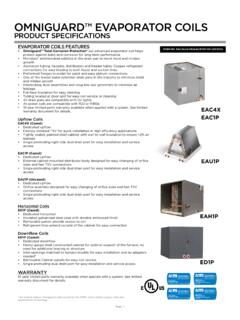
1 FORM NO. MHP4-100 (08/2021)* Check that equipment complies with all applicable building codes, laws, and regulations for its intended use prior to 1 HEAT PUMP / ELECTRIC HEATPACKAGED UNITMHP4-12/14M-SERIES MODEL NUMBER GUIDEREVISION CODEP = 208/230 V - 1 PH - 60 HZC = COIL CORROSION PROTECTION & VENTILATION AIRF = VENTILATION AIRSERIESNOMINAL COOLING CAPACITY09 = 9,000 BTU/HR12 = 12,000 BTU/HR 18 = 18,000 BTU/HR 24 = 24,000 BTU/HR 30 = 30,000 BTU/HR 36 = 36,000 BTU/HRFACTORY INSTALLED ELECTRIC HEAT3= 3 KW5 = 5 KW7 = 7 KW10 = 10 KWM = MAGICPAKHP = HEAT PUMP / ELECTRIC H E AT4 = R-410A REFRIGERANT12 = 12 SEER14 = 14 SEER3 M HP 4 - 12 - 18 1 F P - 13 M HP 4 - 12 - 18 1 F P - 1- Page 2 -MHP4-12/14M-SERIES CONTENTSAPPLICATIONS ..3 UNIT APPROVALS ..3 WARRANTY ..3 STANDARD FEATURES ..3 OPTIONS & ACCESSORIES ..4 FACTORY-INSTALLED OPTIONS ..4 FIELD-INSTALLED ACCESSORIES ..5 UNIT ELECTRICAL AND PHYSICAL DATA.
2 6 UNIT DIMENSIONS (IN.) ..7 MINIMUM CLEARANCES ..8 OUTDOOR SOUND RATING & CABINET AIR LEAKAGE ..9 FACTORY FILTER SIZE (IN.) AND PRESSURE DROP (IN. ) ..9 VENTILATION AIR CAPABILITY ..10 WALL SLEEVES & LOUVERS ..11 SCCR ACCESSORY ..12 CRANKCASE COOLING & HEATING PERFORMANCE ..13 EXTENDED HEATING PERFORMANCE DATA ..13 COMBINED EXTENDED HEATING PERFORMANCE DATA ..14 EXTENDED COOLING PERFORMANCE DATA ..16 BLOWER PERFORMANCE ..17- Page 3 -MHP4-12/14M-SERIES APPLICATIONS MagicPak units are designed for use in all multifamily applications, such as: apartments, condominiums, student housing and senior living Installation in conditioned and non-conditioned mechanical spaces UNIT APPROVALSETL (INTERTEK) Design certified by ETL (Intertek) to latest edition of UL 1995 Certified for the and Canada Certified for less than cabinet air leakage using ASHRAE Standard 193 Factory-installed electric heaters are ETL listed for the and Canada Rated with a 5kA Short Circuit Current Rating (SCCR) in accordance with RMS Symmetrical per UL 508A Refer to Unit Electrical and Physical Data table for additional detailsAHRI/DOE Certified to AHRI Standard 210/240-2008.
3 Refer to the AHRI Directory for AHRI certificates Rated and tested in accordance with DOE test procedures and Federal Trade Commission (FTC) labeling regulationsCORROSION PROTECTION Epoxy coating is specifically designed for use on HVAC type coils and demonstrates 6800+ hours of Sea Water Acetic Acid Testing (SWAAT) per ASTM G85:A3 SOUND RATING Outdoor sound level measurements tested per ANSI/AHRI Standard 270 Refer to Outdoor Sound Rating & Cabinet Air Leakage table for additional detailsALUMINUM LOUVER - PAINT SPECS Standard and impact-resistant louvers meet AAMA 2605 specificationsWARRANTYCOMPRESSOR Five (5) years limited parts warrantyALL OTHER COVERED COMPONENTS Refer to Equipment Limited Warranty for additional detailsSTANDARD FEATURESAIRFLOW CHOICE Factory shipped ready for top supply and return duct connections Return air may be brought in through the optional front return openingNOTE: If ductwork is attached to the optional front return opening, provisions to service unit filter must be providedNOTE.
4 Filter may need to be relocated to a suitable location outside the cabinet for ease of service Ducted or free/non ducted return configuration, which may utilize the top or front as return points Front access panel doubles as cover for top return (except ton)ELECTRICAL CONNECTIONS & GAUGE PORTS Line voltage knockouts (two concentric) to accommodate field required wire size Thermostat connections are located at the top of the cabinet Two gauge ports are located within the lower compartment of the unit Refer to Unit Dimension figure for additional detailsCABINET Embossed galvanized steel cabinet Indoor section of the cabinet insulated with in. dual density fiberglass insulation Outdoor section of the cabinet insulated with in. weather-resistant polystyrene insulationINTERNAL FILTER Tool-less filter access Factory-installed 1 in. filter rack with washable filter Field-supplied filters up to MERV 6 can typically be installed in the filter slot internal to unit in lieu of washable filter, when proper duct design is applied If a higher resistance filter is field installed in the unit, the added resistance must be included in the external static pressure and must not exceed in.
5 Including ductwork Refer to Factory Filter Size and Pressure Drop and Blower Performance tables for additional detailsVENTILATION AIR Units are outfitted with ventilation air openings and are shipped with the openings sealed Refer to Ventilation Air Capability table and Optional Field-Installed Accessories section for additional details Check that equipment complies with all applicable building codes, laws, and regulations for its intended use prior to installation- Page 4 -MHP4-12/14M-SERIES REFRIGERATION SYSTEM Factory charged with R-410A refrigerant Factory sealed and tested Refer to Unit Electrical and Physical Data table for additional detailsIndoor and Outdoor Coils Copper tube with aluminum fin coilsHigh Pressure Switch Shuts off unit if abnormal operating conditions cause the refrigerant discharge pressure to rise above acceptable levelsLow Pressure Switch Provides loss of charge protection by shutting off unit if refrigerant liquid pressure falls below acceptable levelsReversing Valve Reverses the direction of refrigerant flow within the unit s refrigeration circuit.
6 To change between cooling and heating operation Reverses refrigerant flow direction during heat pump defrost cycles to clear outdoor coil of frost buildupDefrost Control Factory mounted sensor determines when defrost cycle starts and ends Anti-short cycle, timed-off control (field-adjustable to 30-90 minutes) is incorporated in the control board The time between defrost cycles is preset at 90-minute intervals at the factory, but can be field adjusted to 30 or 60 minutesLow Ambient Operation Units are not equipped with low ambient compressor cutoffs and can be safely operated to -5 F outdoor ambient temperatures Refer to Extended Heating Performance Data tables for performance data starting at 0 F outdoor ambient temperatureTRANSFORMER Rated for 40VA Factory wired for 230/240V power supply, and includes field selectable terminal for 208V Converts line voltage to 24V for the thermostat and control circuits within the unitSUPPLY AIR BLOWERC onstant Torque ECM Blower Motor Motor provides specified air volume at in.
7 - in. external static pressure Blower assembly is easily removed for servicing Refer to Blower Performance tables for additional detailsElectronic Blower Control Dedicated blower speed taps for continuous fan, cooling, and heating operation are programmed for optimal airflow and controlled by 24V thermostat signals Blower speed adjustment is easily accomplished by speed tap selection Fixed blower delays have been selected to enhance comfort Refer to Blower Performance tables for additional detailsOUTDOOR FAN Heavy duty, fully enclosed and weatherproof Aluminum fan bladesCONDENSATE MANAGEMENT Primary Drain Pan Antimicrobial protection: drain pan is injected with an antibacterial agent that destabilizes the membrane of microorganism cells, disrupting the cellular function of odor-causing mold and bacteria so that they can no longer grow or reproduceOverflow Protection Indoor drain pan overflow switch monitors the condensate level in primary drain pan Prevents unit from running if water is sensedSecondary Drain Pan Polypropylene wall sleeve base is specifically designed to direct rain water out of the building and in the event of any restriction in the primary drain will act as a redundant overflow protectionOPTIONS & ACCESSORIESFACTORY-INSTALLED OPTIONSELECTRIC HEAT Mounted internal to unit cabinet Multiple kW sizes available; must specify the electric heating element size (3kW to 10kW) Optional two stage electric heat wiring on 7 & 10kW.
8 In order to utilize this option, it will require a thermostat with single stage cooling and two stage heating Compatible with 208V, 230V and 240V Helix wound nichrome heating elements exposed directly into the air stream resulting in instant heat transfer and low element temperatures Cutoff limit control provides positive protection in case of excessive temperatures Refer to Rated Cooling & Heating Performance table for additional detailsCORROSION PROTECTION Epoxy coated indoor and outdoor coils- Page 5 -MHP4-12/14M-SERIES FIELD-INSTALLED ACCESSORIESWALL SLEEVES & LOUVERS Units must be installed with approved wall sleeve and louver accessories for safe operation and are required for all installations Larger height wall sleeves may be used on smaller tonnage equipment to maintain a uniform wall opening on the building fa ade Refer to Wall Sleeves and Louvers table for additional detailsWALL SLEEVES (ASLEEVE)
9 Penetrates the building envelope and creates a path for condenser air intake and exhaust Provides a sealed connection to the unit and a secure attachment foundation for the louvers Available in 6 in. to 12 in. depthsWALL SLEEVE EXTENSION (ASLEEVEXT4) Provides an additional 4 in. of depth to the wall sleeve, for a maximum depth of 16 Louvers (ALVRP) Constructed from durable, corrosion-resistant plastic Available in four standard colorsAluminum Louvers (ALVRAL) Constructed with 6063-T6 grade aluminum Available in anodized clear coat, primer (to be painted in the field), standard paint colors and custom colors with paint matching*Impact-Resistant Aluminum Louvers (ALVRALC) Impact and wind load certified up to 186 MPH, risk categories III and IV, and wind exposures C and D ALVRALC-1 & ALVRALC-2: FBC Notice of Acceptance (NOA) ALVRALC-3 & ALVRALC-4: FBC Notice of Acceptance (NOA) Constructed with 6063-T6 grade aluminum Available in anodized clear coat, primer (to be painted in the field), standard paint colors and custom colors with paint matching*CRANKCASE HEATER (ACASE841) Warms compressor crankcase to limit migration of liquid refrigerant back to compressor during off cycle Available for models with scroll compressors Refer to Crankcase Heater table for additional detailsSHORT CIRCUIT CURRENT RATING KIT (ASCCR) Provides 200kA of SCCR protection Refer to SCCR Accessory table for additional detailsFILTERS Field-supplied filters up to MERV 6 can typically be installed in the filter slot internal to unitNOTE.
10 Use of paper frame not recommendedVENTILATION DAMPERS Check that the equipment complies with all applicable building codes, laws, and regulations for its intended use prior to installationMotorized Damper w/ Controller (AVADAMP1) Utilizes a ventilation air control module that is field programmable to assist with meeting ASHRAE requirements Once programmed with values for ventilation air amounts, the control module opens the damper in response to thermostat inputs and monitors the run time Upon meeting the ventilation air needs, the control module will close the damper until the start of the next cycle If, during an observation period it is determined that thermostat operation alone may not provide the desired ventilation air, the control module can independently operate the unit s indoor blower, in continuous fan mode, and open the damper to aid in providing ventilation air needsMotorized Damper w/ Field-Supplied Relay (AVADAMP2)