Transcription of MICHELSON’S INTERFEROMETER - NISER
1 Last updated in Dec 2017 NISER Page 1 MICHELSON S INTERFEROMETER Objectives: 1. Alignment of Michelson s INTERFEROMETER using He-Ne laser to observe concentric circular fringes 2. Measurement of the wavelength of He-Ne Laser and Na lamp using circular fringes 3. Study of fringes of equal inclination and equal thickness using Na lamp Introduction The instruments based upon the principle of interference are called interferometers. These are basic optical tools used to precisely measure wavelength, distance, index of refraction, and temporal coherence of optical beams etc.
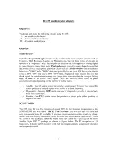
2 It is an amplitude-splitting interferometers devised by Albert Michelson in 1890, the first American physicist to receive the Nobel Prize (1907 for work in optics). Michelson and Morley used this INTERFEROMETER in their celebrated series of experiments designed to demonstrate the existence of the ether. It is still an important instrument in today's laboratories and it is being widely used as an instrument for measuring the wavelength of an unknown light source, to measure extremely small distance and for investigating optical media. Construction: Construction of Michelson INTERFEROMETER is shown in Fig.
3 1. It consists of two highly polished mirrors M1 and M2. Two glass plates beam splitter (BS) and compensatory glass plate (CP), are placed parallel to each other between the mirrors at an angle of 450. The rear side of glass plate BS is semi -silvered such that the light from a source is equally reflected and E Fig. 1 : Construction of Michelson s INTERFEROMETER Last updated in Dec 2017 NISER Page 2 transmitted by it. In this way division of amplitude takes place. From a broad source, let a monochromatic light of wavelength fall on BS.
4 Half of light falling on BS is reflected towards the mirror M1 and the other half is transmitted towards mirror M2. Hence BS is known as a beam splitter. In case of sources which are not monochromatic, the glass plate CP is inserted between BS and M2. The role of CP is explained further in the following paragraph. After splitting, the two rays are reflected back by the mirrors M1 and M2 and return to the plate BS. The ray reflected from M1 is transmitted through BS and the ray reflected from M2 is reflected again by BS.
5 The two rays coming from the two mirrors interfere and fringes are observed on a screen (for laser) or by naked eye (Na lamp) at E. Usually one of the mirrors is mounted on a translation stage so that it can be moved back and forth to observe the change in fringes. Optical path The rays falling on mirrors M1 and M2 are derived from the same source originally incident on plate BS (see Fig. 1). The wave reflected from M1 and entering the eye crosses BS twice. However the path of the other wave falling on the mirror M2, in the absence of compensating plate CP, travels totally in air.
6 Thus an extra optical path 2( -1)t is introduced where, 't' is the thickness of the plate and is the refractive index of the BS plate for the monochromatic light used. Presence of CP is not essential if fringes are produced with monochromatic light. But it produces a serious problem when white light is used. Thus, it becomes necessary to compensate for the extra optical path 2( -1)t for all wavelengths. This is done by introducing another glass plate CP of same thickness as that of BS parallel to it. Thus, the two waves will interfere constructively or destructively as per the following conditions of path difference, : = 2n /2 = n (for maxima, n is an integer) = (2n+1) /2 (for minima, n is an integer) Types of fringes: Path difference between the two rays can be varied by moving M1.
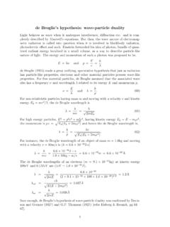
7 Mirror M1 and the virtual image of mirror M2 act as the two surfaces of an air film. The fringes formed in Michelson INTERFEROMETER may be circular, curved or straight depending upon the nature of the air film. Last updated in Dec 2017 NISER Page 3 Concentric circular fringes (fringes of equal inclination): Concentric circular fringes are obtained when the air film is parallel as shown in Fig. 2. M2' is the virtual image of M2 and it is parallel to M1. For simplicity, light source L is at the observer's position. L1 and L2 are the virtual images of L formed by M1 and M2', and are coherent.
8 Let d be the distance between M1 and M2', therefore the distance between L1 and L2 is 2d. Let be the angle between the incident beam originated at P and the reflected beams from M1 and M2'. Then path difference between light beams from points P and P" is 2d cos . A maximum (bright fringe) will be formed when 2dcos = n . For a fixed value of n, and d, the value of is a constant, and the contour of the maximum point becomes a ring. The centre of the ring is in line with the observer and perpendicular to the mirror plane. Each circular ring corresponds to a particular value of.
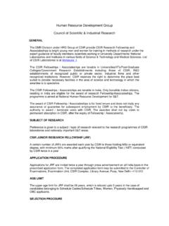
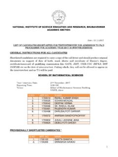
9 Hence the fringes are known as fringes of equal inclination. Fig. 2: Formation of circular fringes Curved fringes (fringes of equal thickness): When M1 and virtual image M2' are inclined to each other, the film enclosed is wedge shaped. Then curved fringes can be observed as shown in Fig. 3. These are also known as fringes of equal thickness. Fig. 3: Formation of curved fringes Straight line fringes: When M1 and virtual image M2' intersect, straight line fringes are obtained around the point of intersection (see Fig. 4). The path P P P L1 L2 P P 2d cos 2d Fig.
10 4: Formation of straight line fringes Last updated in Dec 2017 NISER Page 4 difference along the line of intersection is zero and therefore, is same for all the wavelengths. When a source of white light is used we get central achromatic bright fringe. On either side of central fringe, few coloured straight fringes are observed. Determination of from circular fringes: Circular fringes are used to determine the wavelength of the source of light. For a given separation of d between the mirrors M1 and M2 and normal incidence ( =0), the path difference is given as 2d = n.