Transcription of Microcontroller based speed control of three phase ...
1 International Journal of Scientific and Research Publications, Volume 3, Issue 2, February 2013 1 ISSN 2250-3153 Microcontroller based speed control of three phase induction motor using v/f method , Prof. , Electrical Dept. PES s Modern College of Engg. Pune Abstract- Induction motors are widely used AC motors in industrial area. Advanced semiconductor technology & use of Microcontroller have made the speed control of induction motor easier. The proposed paper represents variable speed control application of induction motor using v/f method. In this system, the speed of the induction motor can be adjusted to user defined speed .
2 The actual speed & reference speed is compared & the difference is adjusted by changing the firing angles of IGBTs. The system is tested & experimental results are recorded for variable speed under various load conditions. Index Terms- Inverter, rectifier, Microcontroller , squirrel cage induction motor. I. INTRODUCTION n industrial drive system basically consists of a mechanical working equipment, or load, which can be kept in motion to turn out mechanical work with the help of prime mover. To transfer energy from prime mover to mechanical load gearing or belt may be used. The transmission may also be required to convert rotary to linear motion and vice versa.
3 Thus a combination of prime mover, transmission equipment, and mechanical working load is called a DRIVE. An electric drive can be defined as a drive, using an electric motor as a prime mover. The electric motors used may require some types of control equipment to achieve speed control and torque control . These controls make the motor work on a specific speed torque curve and may be operated using open loop or closed loop control . II. PROPOSED WORK AND ANALYSIS The present work makes use of DSPIC30F2010 Microcontroller , in order to operate induction motor using V/F method.
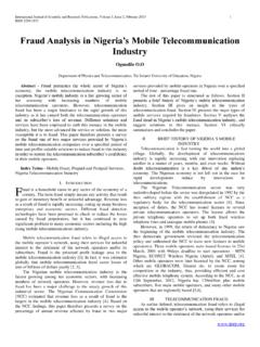
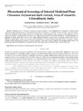
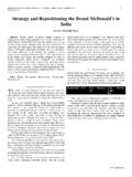
4 The various factors which make the Microcontroller based system attractive are, 1. Improved reliability and increased flexibility. 2. Simplicity of implementation in variable speed drives 3. Low cost and high accuracy 4. Possible to change torque speed characteristics of drive by software modification. The simplicity of this project is that it can be operate by any person who need not know Microcontroller programming. Block Diagram: Fig. 1 Block diagram of system shows the block diagram of closed loop control of induction motor using Microcontroller DSPIC30F2010.
5 The hardware includes squirrel cage induction motor, rectifier, bridge inverter, Microcontroller , speed sensor, and switches for user interface. As shown in the figure single phase supply is given to the rectifier, rectifier DC output is given to inverter & three phase squirrel cage induction motor is connected to the three phase supply, which is the output of the inverter. speed of the motor is sensed by sensor and feedback is given to Microcontroller , Microcontroller generates error signal send it to inverter. three phase supply generated by the inverter drives the motor at user defined speed .
6 Design specification for each block are given below, Design Specifications:- 1. Rectifier Block: - A bridge of Diodes Diode Rating: - 3 Amp/1000V A Rectifier Unit Bridge Inverter 1ph. AC Supply Micro Controller speed Sensor speed Display 3 ph. I. M. International Journal of Scientific and Research Publications, Volume 3, Issue 2, February 2013 2 ISSN 2250-3153 375 Watt Current passing through diodes = ------------- = Amp. 440 V Output Voltage of bridge rectifier = 440V x = 622 V Diode PIV should be greater than 622V (with +/- 10% tolerance) 2.
7 Capacitor Bank:- Selected Rating :- 470 F/450V 2series, 2parallel 375 Watt Current = ----------- = Amp. 622V for 1 Amp 1000 F is used by thumb rule so for Amp 500 F is used. 3. IGBT:- Selected Rating: - 60A/900V IGBT voltage > 622V IGBT current > 4. three phase Squirrel Cage Induction Motor with mechanical load arrangement (375 watt), 3 phase , 1 Amp, 440V, 1440 rpm III.
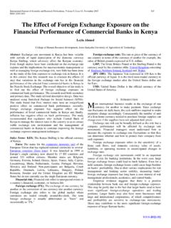
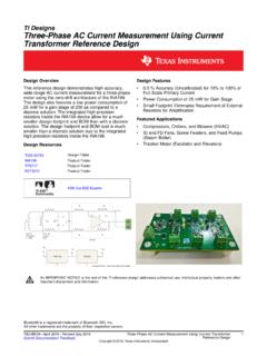
8 IMPLEMENTATION In this project we have selected uncontrolled bridge rectifier, voltage control inverter, and squirrel cage induction motor, DSpic2010 Microcontroller . Initially user select the speed range from three modes s1=1440 s2=1200 , s3= with the help of start key. After selection of the speed range, with increase in the supply voltage motor reaches to reference speed at no-load. With increase in the load gradually the motor speed start to drop, this speed is sensed by speed sensor & converted to voltage in feedback circuit. The actual speed is compared with set speed in controller & if the speed is less than set speed , controller decrease the total time period (T) of PWM so t/T increases and the output voltage of PWM Vout = [( t/T) x Vin] increases.
9 In this way the PWM waveform generated by inverter drives the induction motor at set speed by keeping v/f ratio constant. shows total period of the PWM pulse. t T t PWM Output Voltage =------- * Vin T Where, t = ON time (which is constant)
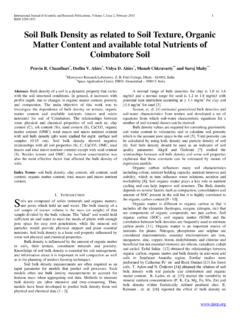
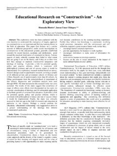
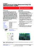
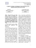
10 T = Total time period Vin = Supply Voltage The speed of the motor, terminal voltage of the motor, supply frequency & also v/f ratio has been displayed. Flowchart:- International Journal of Scientific and Research Publications, Volume 3, Issue 2, February 2013 3 ISSN 2250-3153 Main Circuit: YES