Transcription of Microcontroller - Farnell element14
1 Features High-performance, Low-power atmel avr XMEGA 8/16-bit Microcontroller Non-volatile Program and Data Memories 16K - 128 KBytes of In-System Self-Programmable Flash 4K - 8 KBytes Boot Code Section with Independent Lock Bits 1K - 2 KBytes EEPROM 2K - 8 KBytes Internal SRAM Peripheral Features Four-channel DMA Controller Eight-channel Event System Five 16-bit Timer/CountersThree Timer/Counters with 4 Output Compare or Input Capture channelsTwo Timer/Counters with 2 Output Compare or Input Capture channelsHigh-Resolution Extensions on all Timer/CountersAdvanced Waveform Extension on one Timer/Counter One USB device InterfaceUSB full speed (12 Mbps) and low speed ( ) device compliant32 Endpoints with full configuration flexibility Five USARTs with IrDA support for one USART Two Two-Wire Interfaces with dual address match (I2C and SMBus compatible) Two Serial Peripheral Interfaces (SPIs) AES and DES Crypto Engine CRC-16 (CRC-CCITT) and CRC-32 (IEEE ) Generator 16-bit Real Time Counter with Separate Oscillator One Twelve-channel, 12-bit, 2 MSPS Analog to Digital Converter One Two-channel, 12-bit, 1 MSPS Digital to Analog Converter Two Analog Comparators with Window compare function, and current source feature External Interrupts on all General Purpose I/O pins Programmable Watchdog Timer with Separate On-chip Ultra Low Power Oscillator QTouch library supportCapacitive touch buttons, sliders and wheelsUp to 64 sense channels Special Microcontroller Features Power-on Reset and Programmable Brown-out Detection Internal and External Clock Options with PLL and Prescaler Programmable Multi-level Interrupt Controller Five Sleep Modes Programming and Debug InterfacesPDI (Program and Debug Interface)
2 I/O and Packages 34 Programmable I/O Pins 44 - lead TQFP 44 - pad VQFN/QFN 49 - ball VFBGA Operating Voltage Operating Frequency 0 12 MHz from 0 32 MHz from Applications Industrial control Climate control Low power battery applications Factory automation RF and ZigBee Power tools Building control USB Connectivity HVAC Board control Sensor control Utility Metering White Goods Optical Medical Applications8/16-bit AtmelXMEGA A4 UMicrocontrollerATxmega128A4 UATxmega64A4 UATxmega32A4 UATxmega16A4 UPreliminary 8387A AVR 07/1128387A AVR 07/11 XMEGA A4U1. Ordering InformationNotes:1. This device can also be supplied in wafer form. Please contact your local Atmel sales office for detailed ordering Pb-free packaging, complies to the European Directive for Restriction of Hazardous Substances (RoHS directive). Also Halide free and fully For packaging information see Packaging information on page CodeFlash (Bytes) EEPROM (Bytes) SRAM (Bytes)Speed (MHz)Power SupplyPackage(1)(2)(3)TempATxmega128A4U- AU128K + - C - 85 CATxmega64A4U-AU64K + 4K2K4 KATxmega32A4U-AU32K + 4K1K4 KATxmega16A4U-AU16K + 4K1K2 KATxmega128A4U-MH128K + 8K2K8K44M1 ATxmega64A4U-MH64K + 4K2K4 KATxmega32A4U-MH32K + 4K1K4 KATxmega16A4U-MH16K + 4K1K2 KATxmega128A4U-CU128K + 8K2K8K49C2 ATxmega64A4U-CU64K + 4K2K4 KATxmega32A4U-CU32K + 4K1K4 KATxmega16A4U-CU16K + 4K1K2 KPackage Type44A44-Lead, 10 x 10mm Body Size, Body Thickness, Lead Pitch, Thin Profile Plastic Quad Flat Package (TQFP)44M144-Pad, 7x7x1mm Body, Lead Pitch , Exposed Pad, Thermally Enhanced Plastic Very Thin Quad No Lead Package (VQFN)49C249-Ball (7 x 7 Array), Pitch, x x , Very Thin, Fine-Pitch Ball Grid Array Package (VFBGA)
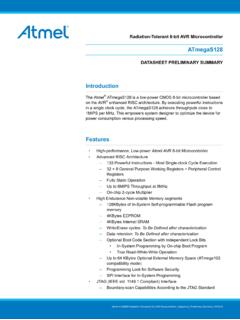
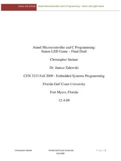
3 38387A AVR 07/11 XMEGA A4U2. Pinout/Block Diagram Figure Diagram and QFN/TQFP pinoutNote:For full details on pinout and pin functions refer to Pinout and Pin Functions on page / GroundDigital functionAnalog functionProgramming, debug, testExternal clock / Crystal pinsGeneral Purpose I/O1234444342414039385678910113332313029 2827262524233736353412131415161718192021 22PA0PA1PA2PA3PA4PB0PB1PB3PB2PA7PA6PA5 GNDVCCPC0 VDDGNDPC1PC2PC3PC4PC5PC6PC7PD0PD1PD2PD3P D4PD5PD6 VCCGNDPD7PE0PE1PE2PE3 RESET/PDIPDIPR0PR1 AVCCGNDP ower SupervisionPort AEVENT ROUTING NETWORKDMAC ontrollerBUSmatrixSRAMFLASHADCAC0:1 OCDPort EPort DProg/DebugInterfaceEEPROMPort CTC0:1 Event System ControllerWatchdog TimerWatchdogOSC/CLK ControlReal TimeCounterInterrupt ControllerDATA BUSDATA BUSPort RUSART0:1 TWISPITC0:1 USART0:1 SPITC0 USART0 TWIPort BDACAREFAREFS leep ControllerResetControllerTEMPREFVREFIRCO MC rypto / CRCUSBCPU48387A AVR 07/11 XMEGA A4 UFigure pinoutTable pinout123456 APA3 AVCCGNDPR1PR0 PDI_DATAPE3 BPA 4PA 1PA 0G N DRESET/PDI_CLKPE2 VCCCPA5PA2PA6PA7 GNDPE1 GNDDPB1PB2PB3PB0 GNDPD7PE0 EGNDGNDPC3 GNDPD4PD5PD6 FVCCPC0PC4PC6PD0PD1PD3 GPC1PC2PC5PC7 GNDVCCPD2 ABCDEFG1234567 ABCDEFG7654321 Top viewBottom view58387A AVR 07/11 XMEGA A4U3.
4 OverviewThe atmel avr XMEGA is a family of low power, high performance and peripheral rich 8/16-bit microcontrollers based on the AVR enhanced RISC architecture. By executing instructionsin a single clock cycle, AVR achieves throughputs CPU approaching 1 Million Instructions PerSecond (MIPS) per MHz allowing the system designer to optimize power consumption versusprocessing AVR CPU combines a rich instruction set with 32 general purpose working registers. Allthe 32 registers are directly connected to the Arithmetic Logic Unit (ALU), allowing two indepen-dent registers to be accessed in one single instruction, executed in one clock cycle. Theresulting architecture is more code efficient while achieving throughputs many times faster thanconventional single-accumulator or CISC based XMEGA A4U devices provide the following features: In-System Programmable Flash withRead-While-Write capabilities, Internal EEPROM and SRAM, four-channel DMA Controller,eight-channel Event System, Programmable Multi-level Interrupt Controller, 34 general purposeI/Opins, 16-bit Real Time Counter, five flexible 16-bit Timer/Counters with compare and PWMchannels, one USB full speed (12 Mbps) Device Interface, five USARTs, two Two Wire SerialInterfaces (TWIs), two Serial Peripheral Interfaces (SPIs), AES and DES crypto engine, oneTwelve-channel, 12-bit ADC with optional differential input with programmable gain, one Two-channel 12-bit DAC, two analog comparators with window mode, programmable WatchdogTimer with separate Internal Oscillator, accurate internal oscillators with PLL and prescaler andprogrammable Brown-Out Program and Debug Interface (PDI), a fast 2-pin interface for programming and debugging,is available.
5 All XMEGA devices have five software selectable power saving modes. The Idle mode stops theCPU while allowing the SRAM, DMA Controller, Event System, Interrupt Controller and allperipherals to continue functioning. The Power-down mode saves the SRAM and register con-tents but stops the oscillators, disabling all other functions until the next TWI or pin-changeinterrupt, or Reset. In Power-save mode, the asynchronous Real Time Counter continues to run,allowing the application to maintain a timer base while the rest of the device is sleeping. InStandby mode, the Crystal/Resonator Oscillator is kept running while the rest of the device issleeping. This allows very fast start-up from external crystal combined with low power consump-tion. In Extended Standby mode, both the main Oscillator and the Asynchronous Timer continueto run. To further reduce power consumption, the peripheral clock to each individual peripheralcan optionally be stopped in Active mode and Idle sleep offers the QTouch library for embedding capacitive touch buttons, sliders and wheelsfunctionality into AVR device is manufactured using Atmel's high-density nonvolatile memory technology.
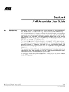
6 The pro-gram Flash memory can be reprogrammed in-system through the PDI. A Bootloader running inthe device can use any interface to download the application program to the Flash memory. TheBootloader software in the Boot Flash section will continue to run while the Application Flashsection is updated, providing true Read-While-Write operation. By combining an 8/16-bit RISCCPU with In-System Self-Programmable Flash, the Atmel XMEGA A4U is a powerful microcon-troller family that provides a highly flexible and cost effective solution for embedded AVR 07/11 XMEGA A4 UThe atmel avr XMEGA devices are supported with a full suite of program and systemdevelopment tools including: C compilers, macro assemblers, program debugger/simulators,programmers, and evaluation DiagramFigure A4U Block DiagramPower SupervisionPOR/BOD & RESETPORT A (8)PORT B (8)DMAC ontrollerSRAMADCAACADACBOCDInt. [ ]PB[ ]Watchdog TimerWatchdogOscillatorInterrupt ControllerDATA BUSProg/DebugControllerVCCGNDO scillator Circuits/ ClockGenerationOscillator ControlReal TimeCounterEvent System ControllerAREFAAREFBPDI_DATARESET/PDI_CL KS leep ControllerDESCRCPORT C (8)PC[ ]TCC0:1 USARTC0:1 TWICSPICPD[ ]PE[ ]PORT D (8)TCD0:1 USARTD0:1 SPIDTCE0 USARTE0 TWIEPORT E (4)TemprefAESUSBPORT R (2)DATA BUSNVM ControllerMORPEE hsalFIRCOMBUS MatrixCPUEVENT ROUTING NETWORKXTAL1/TOSC1 XTAL2/TOSC2PR[ ]TOSC1 (optional)TOSC2(optional)Digital functionAnalog functionProgramming, debug, testOscillator/Crystal/ClockGeneral Purpose I/O78387A AVR 07/11 XMEGA A4U4.
7 ResourcesA comprehensive set of development tools, application notes and datasheets are available fordownload on reading XMEGA AU Manual XMEGA Application NotesThis device data sheet only contains part specific information with a short description of eachperipheral and module. The XMEGA AU Manual describes the modules and peripherals indepth. The XMEGA application notes contain example code and show applied use of the mod-ules and documentations are available from Capacitive touch sensingThe Atmel QTouch Library provides a simple to use solution to realize touch sensitive inter-faces on most atmel avr microcontrollers . The patented charge-transfer signal acquisitionoffers robust sensing and includes fully debounced reporting of touch keys and includes Adja-cent Key Suppression (AKS ) technology for unambiguous detection of key events. TheQTouch Library includes support for the QTouch and QMatrix acquisition sensing can be added to any application by linking the appropriate Atmel QTouch Libraryfor the AVR Microcontroller .
8 This is done by using a simple set of APIs to define the touch chan-nels and sensors, and then calling the touch sensing API s to retrieve the channel informationand determine the touch sensor QTouch Library is FREE and downloadable from the Atmel website at the following For implementation details and other information, refer to theAtmel QTouch Library User Guide - also available for download from the atmel avr 07/11 XMEGA A4U6. AVR 8/16-bit high performance AVR RISC Architecture 142 instructions Hardware multiplier 32x8-bit registers directly connected to the ALU Stack in SRAM Stack Pointer accessible in I/O memory space Direct addressing of up to 16 Mbytes of program and 16 Mbytes of data memory True 16/24-bit access to 16/24-bit I/O registers Support for 8-, 16- and 32-bit Arithmetic Configuration Change Protection of system critical atmel avr XMEGA devices use the 8/16-bit AVR CPU.
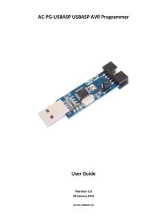
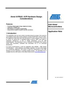
9 The main function of the CPU isto execute the code and perform all calculations. The CPU is able to access memories, performcalculations, control peripherals, and execute the program from the FLASH memory. Interrupthandling is described in a separate section, refer to Interrupts and Programmable Multi-levelInterrupt Controller on page 26. Figure 6-1 on page 8 shows the CPU block diagram of the AVR CPU Diagram of the AVR CPU architectureIn order to maximize performance and parallelism, the AVR uses a Harvard architecture withseparate memories and buses for program and data. Instructions in the program memory areexecuted with a single level pipelining. While one instruction is being executed, the next instruc-98387A AVR 07/11 XMEGA A4 Ution is pre-fetched from the Program Memory. This enables instructions to be executed in everyclock program memory is In-System Self-Programmable Flash - Arithmetic Logic UnitThe Arithmetic Logic Unit (ALU) supports arithmetic and logic operations between registers orbetween a constant and a register.
10 Single register operations can also be executed. The ALUoperates in direct connection with all the 32 general purpose registers. In a single clock cycle,arithmetic operations between general purpose registers or between a register and an immedi-ate are executed and the result is stored back in the Register File. After an arithmetic or logicoperation, the Status Register is updated to reflect information about the result of the operation. The ALU operations are divided into three main categories arithmetic, logical, and bit-func-tions. Both 8- and 16-bit arithmetic is supported, and the instruction set allows for efficientimplementation of 32-bit arithmetic. The hardware multiplier supports signed and unsigned mul-tiplication and fractional FlowAfter reset, the CPU starts to execute instructions from the lowest address in the Flash ProgramMemory 0 . The Program Counter (PC) addresses the next instruction to be fetched.