Transcription of MICROWAVE OVEN BUILT-IN TRIM KIT INSTALLATION …
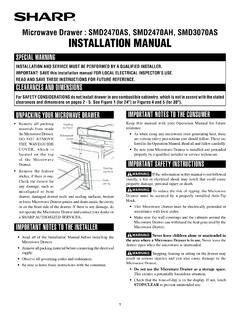
1 MICROWAVE OVEN BUILT-IN TRIM KITINSTALLATION INSTRUCTIONSB uilt-In Trim Kit Models MK2227 MK2220UL listed for use over any electric or gas BUILT-IN oven, up to 30" ( cm) wideINSTRUCTIONS D INSTALLATIONGARNITURE ENCASTR E POUR FOUR MICRO-ONDESG arniture encastr e pour mod les MK2227 MK2220 Homologations UL pour utilisation au-dessus de tous les fours encastr s lectriques ou gaz, jusqu 30" (76,2 cm) de largeurMICROWAVE OVEN SAFETYT able of Contents / Table des mati resMICROWAVE OVEN SAFETY ..1 INSTALLATION and Parts ..2 Location Requirements ..2 Required Cutout Kit Frame Requirements ..3 Prepare MICROWAVE Cutout/Cabinet Opening.
2 3 Install the MICROWAVE Trim Kit Frame ..5S CURIT DU FOUR MICRO-ONDES .. 7 INSTRUCTIONS D INSTALLATION .. 7 Outillage et pi ces .. 7 Exigences d' 7 Dimensions n cessaires de l'ouverture d' 8 Dimensions du cadre de la trousse de garniture .. 8Sp cifications lectriques ..8Pr paration du four 9Pr paration de l'ouverture d'encastrement/dans le placard .. 9 INSTALLATION du four micro-ondes ..10 INSTALLATION du cadre de la trousse de garniture ..11W10434148 AYou can be killed or seriously injured if you don't immediately You can be killed or seriously injured if you don'tfollow All safety messages will tell you what the potential hazard is, tell you how to reduce the chance of injury, and tell you what canhappen if the instructions are not safety and the safety of others are very have provided many important safety messages in this manual and on your appliance.
3 Always read and obey all safety is the safety alert symbol alerts you to potential hazards that can kill or hurt you and safety messages will follow the safety alert symbol and either the word DANGER or WARNING. These words mean:follow INSTRUCTIONST ools and PartsTools NeededGather the required tools and parts before starting INSTALLATION . Read and follow the instructions provided with any tools listed Supplied (not shown to scale) Location RequirementsThe MICROWAVE oven may be installed over a BUILT-IN oven. If installing over a BUILT-IN oven, make sure there is a minimum of 3" ( cm) between the top of the lower oven cutout and the MICROWAVE oven cutout floor.
4 The MICROWAVE oven may also be installed in a cabinet by itself (without a BUILT-IN oven below). For best usability, we recommend a minimum distance of 36" ( cm) from the floor to the cutout sure the surrounding cabinetry has clearance to open and close freely. Allow a clearance of at least 1 " ( cm) below the cutout floor (3" [ cm] for INSTALLATION above a BUILT-IN oven), and a clearance of at least 2" ( cm) above the cutout Cutout DimensionsNOTES: Height dimension is critical: 17" ( cm) minimum, 17 " ( cm) maximum. Width and depth measurements have 1/16" (2 mm) tolerance. 3" ( cm) minimum dimension is from lower oven cutout ceiling to MICROWAVE oven cutout floor.
5 Trim kit frame extends 1 " ( cm) above and below the cutout Kit Frame Dimensions*27" ( cm) trim kit**30" ( cm) trim kit Measuring tape Pencil Phillips screwdriver Drill 7/64" drill bitRails (2)Bottom ductTrim kit frameShort screws (14)(11 + 3 extra)Long wood screws (6 - painted)(4 + 2 extra)A. Upper cabinetB. MICROWAVE oven cutoutC. Lower oven cutoutD. Lower cabinetsE. Floor3"( cm)BBD36"( cm)C2"( cm)2"( cm)1 "( cm)AEA. Trim kit frame overhangB. Cutout for lower oven22 "( cm)WidthWidth25 " ( cm)3"( cm)A1 "( cm)1 "( cm)B17 " ( cm) " ( cm) " ( cm)**29 " ( cm)** " ( cm)**2 " ( cm)**25" ( cm)13 "( cm)1" ( cm)18 "( cm)2 "( cm)3 Electrical RequirementsObserve all governing codes and : A 120 volt, 60 Hz, AC only, 15- or 20-amp electrical supply with a fuse or circuit : A time-delay fuse or time-delay circuit breaker.
6 A separate circuit serving only this MICROWAVE MICROWAVE MICROWAVE oven before proceeding with any loose items inside MICROWAVE turn MICROWAVE oven onto its top, with the door facing forward (toward installer). the #33 holes on the MICROWAVE oven bottom with the #33 holes on the rails, as shown, making sure the flanges are forward and pointing the rails to the MICROWAVE oven bottom using four short screws through the #33 hole Cutout/Cabinet the cutout floor, find and mark the the bottom duct in the opening, with the flange resting against the bottom front facing of the Shock HazardPlug into a grounded 3 prong not remove ground not use an not use an extension to follow these instructions can result in death, fire, or electrical INSTRUCTIONSSAVE THESE INSTRUCTIONS For all cord connected appliances.
7 The MICROWAVE oven must be grounded. In the event of an electrical short circuit, grounding reduces the risk of electric shock by providing an escape wire for the electric current. The MICROWAVE oven is equipped with a cord having a grounding wire with a grounding plug. The plug must be plugged into an outlet that is properly installed and : Improper use of the grounding plug can result in a risk of electric shock. Consult a qualified electrician or serviceman if the grounding instructions are not completely understood, or if doubt exists as to whether the MICROWAVE oven is properly grounded. Do not use an extension cord. If the power supply cord is too short, have a qualified electrician or serviceman install an outlet near the MICROWAVE Rails (2)B.
8 MICROWAVE oven bottomC. Short screws (4)D. FlangesE. DoorA. Cutout floorB. CenterlineC. Bottom ductD. Bottom duct flangeE. Front facingAB the center arrows on the bottom duct with the centerline drawn in Step 1 the three mounting holes through the bottom duct onto the cutout 7/64" drill, drill pilot holes into the three holes marked in Step and install the bottom duct with three short screws. 7/64" drill, drill pilot holes through the four mounting holes of the bottom duct flange into the bottom front facing of the cutout/cabinet the MICROWAVE return MICROWAVE oven to its upright MICROWAVE oven near cutout in MICROWAVE the rails with the rail guides on the bottom Bottom ductB.
9 Center arrows, aligned with centerlineA. Short screws (3)B. Bottom duct mounting holesA. Bottom duct flangeB. Mounting holesABABABA. Rail guidesB. RailsElectrical Shock HazardPlug into a grounded 3 prong not remove ground not use an not use an extension to follow these instructions can result in death, fire, or electrical the MICROWAVE oven back and into place. The mounting holes of the rail flanges and bottom duct flange will align against the bottom front facing of the cutout/cabinet the MICROWAVE oven to the cutout/cabinet by installing four short screws into the mounting Trim Kit trim kit frame over the opening so that the lower tabs rest on the cutout floor, as shown.
10 The trim kit frame in place, use 7/64" drill to drill four pilot holes into the front facing of the cutout/cabinet through the mounting hole guides in the upper and lower corners of the trim kit : The holes will be drilled downward from the top, and upward from the bottom at an angle of about 45 . To avoid damage to the trim kit frame, do not overtighten screws. trim kit frame to cutout/cabinet by installing four long wood screws (painted) into the pilot holes drilled in Step 2 is now complete. Replace any loose items that have been removed from MICROWAVE oven these INSTALLATION Instructions for future Mounting holesB. Short screws (4)A.