Transcription of MIL-DTL-38999, Series II JT Amphenol Aerospace MIL-DTL ...
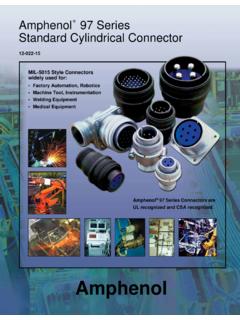
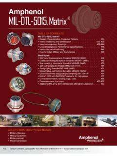
1 61 contact Amphenol Aerospace for more information at 800-678-0141 Dualok IIISJT 38999 I HD Fiber OpticsContactsConnectorsCablesHIgH SPEED26482 Matrix 2 83723 IIIM atrix|Pyle5015 Crimp RearRelease Matrix26500 Pyle 22992 Class L Back- ShellsOptions OthersEMI FilterTransientPCB AccessoriesAquaconHerm/SealAmphenolAeros paceAmphenol LJT and JT Series subminiature cylindrical connectors are qualified to MIL-DTL - 38999 *, Series I and II respectively. These con nectors were developed to meet the needs of the Aerospace industry, and provided the impetus for development of the MIL-C- 38999 specifications, which has been superseded by MIL-DTL - 38999 . Meeting or exceeding MIL-DTL - 38999 requirements, Amphenol JT/LJT connectors feature: MIL-DTL - 38999 , Series II JT MIL-DTL - 38999 , Series I LJT ComponentsShell components are impact extruded or machined bar stock aluminum. Standard plating on shell com ponents is cadmium over nickel.
2 Many finishes are optional (see Specifications page 19). Hermetic seal receptacles are available in carbon steel or stainless steel shells. Dependable 5 key/keyway polarization with bayonet lock coupling is incorpo rated to aid and assure positive material is a rigid dielectric with excellent electrical character-istics, providing durable protec tion for molded-in solder type contacts. Contrasting letter or number designations are used on insert fluorinated silicone interfacial seal wafer is fea tured on the mating face of crimp type pin inserts. This assures complete electrical isolation of pins when connector halves are mated. In addition, a main joint gasket is installed in the receptacle for moisture sealing between connector halves. Both features are also available for hermetic design flexibility is built into the JT/LJT Series , with a mini-mum of 2 to a maximum of 128 circuits per connector in a wide variety of contact arrangements.
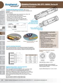
3 Contacts are available in sizes 8, 10, 12, 16, 20, 22, 22D and 22M with standard 50 micro inch minimum gold plating (100 micro inches optional). All socket contacts are probe proof. Crimp type rear removable contacts are featured in JT-R and LJT-R connectors. Solder termination contacts are also available, as well as PCB, wire wrap, thermocouple, fiber optic, coaxial, triaxial and twinax contact FeaturesHigh temperature capability of 392 F is available only in JTS or LJTS crimp type connectors. High temperature versions feature gold plated contacts, high temperature shell plating, stainless steel cou pling nut spring, and epoxy inserts/fluorinated sili cone grommet combination. Standard temperature capability for both solder and crimp is 302 JTN or LJTN type connectors are available for N2O4resistance provided they are mated, and un-grommeted rear faces are suitably complete listing and definition of connector types, shell styles and service classes, see How to Order, pages 62 & 63.
4 For information on Fail-Safe Lanyard Release style plugs, see pages 94 & Benefits Lightweight, Space Saving Design contact Protection - 100% scoop-proof LJT design prevents bent pins and short circuits dur ing mating Quick Positive Coupling - 3 point bayonet lock system Mismating Eliminated - with 5 key/keyway design Error Proof Alternate Positioning - insured by different key/ keyway locations EMI Shielding - grounding fingers standard in LJT Series ; optional in JT Series Nine Shell Sizes and a Variety of Shell Styles contact Options - size 8, 10, 12, 16, 20, 22M and 22D Crimp, Solder, PCB, Wire wrap, Coax, Twinax, Triax, Thermocouple, Fiber Optic and Fil ter Fixed Solder Contacts - Amphenol MIL-DTL - 38999 Series I LJT and II JT, are available in solder versions as both Commercial and Military qualified to MIL-DTL -27599 Hermetic - air leakage limited to 1 X 10⁻⁷ cm3 per second optional Breakaway Lanyard Release Style - available in LJT plugs.
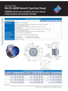
5 Provides quick disconnect of the connector plug and receptacle with axial pull on the lanyard. See pages 94-96. Inventory Support Commonality - uses stan dard MIL-DTL - 38999 contacts, insert arrangements and application tools. RoHS Compliant Product Available - Consult Amphenol Aerospace proof of high reliability and lot control is required, MS approved equivalents to most propri etary JT and LJT connectors are available.* MIL-DTL - 38999 Series I supersedes MIL-C- 38999 Series I. MIL-DTL - 38999 Series II supersedes MIL-C- 38999 Series I LJTMIL-DTL- 38999 Series II JT 62 contact Amphenol Aerospace for more information at 800-678-0141 IIISJT 38999 PCB HD I II AquaconAccessoriesHerm/SealFiber OpticsContactsConnectorsCablesHIgH SPEED26482 Matrix 2 83723 III501526500 Pyle 22992 Class L Back- ShellsOptions OthersEMI FilterTransientCrimp RearRelease MatrixMatrix|PyleAmphenolAerospaceConnec tor Type Series I IIShell StyleService ClassShell Size- Insert ArrangementContact TypeAlternate PositionStrain Relief/Finish Variation SuffixLJTJT00RT9-35 PBSR(014)
6 Series ISeries IIDesignatesJTStandard Junior Tri-LockLJT Long Junior Tri-LockLJTSJTSHigh temperature connectorLJTNJTNC hemical and fuel resistantJTLM iniature mounting dimensionsJTLNM iniature mounting dimensions Chemical resistantJTLSM iniature mounting dimensions High temperatureLJTPQJTPQBack panel mounted wall mounting receptacleLJTPJTPBack panel mounted box mounting receptacleLJTPNJTPNBack panel mounted Chemical resistantLJTPSJTPSBack panel mounted High temperatureJTGPlug with grounding fingers*JTNGPlug with grounding fingers* Chemical resistantEasy Steps to build a commercial part Series I and II 1. 2. 3. 4. 5. 6. 1. Select a Connector TypeConnector TypeShell StyleService ClassShell Size- Insert TypeAlternate PositionSpecial VariationsJT 1. 2. 3. 4. 5. 6. LJTNJTL JTLN JTLS JTPQ JTP JTPN JTPS LJTPQ LJTP LJTPN LJTPSJTG JTNGD esignates0000 Wall mount receptacle (Hermetic option)01 Line mount receptacle (Non-hermetic)0202 Box mount receptacle (Hermetic Option except for LJT)0606 Straight plug (Non-hermetic)0707 Jam nut receptacle (Hermetic Option)080890 degree plug (Non-hermetic)ISolder mount receptacle (hermetic)Step 2.
7 Select a Shell StyleConnector TypeShell StyleService ClassShell Size-Insert TypeAlternate PositionSpecial Variations00 1. 2. 3. 4. 5. 6. Mounting ReceptacleLine ReceptacleJam Nut ReceptacleStraight PlugSolder Mounting ReceptacleLanyard Release PlugWall Mounting ReceptacleBox Mounting ReceptacleStraight PlugJam Nut Receptacle90 PlugSolder Mounting ReceptacleSeries I LJTS eries II JTMIL-DTL- 38999 / 27599, Series II JT MIL-DTL - 38999 / 27599, Series I LJT*Grounding fingers standard on all LJT plugsHow to Order (Commercial)(See pages 94-96 for ordering)63 contact Amphenol Aerospace for more information at 800-678-0141 Dualok IIISJT 38999 I HD Fiber OpticsContactsConnectorsCablesHIgH SPEED26482 Matrix 2 83723 IIIM atrix|Pyle5015 Crimp RearRelease Matrix26500 Pyle 22992 Class L Back- ShellsOptions OthersEMI FilterTransientPCB AccessoriesAquaconHerm/SealAmphenolAeros paceSeries I LJTS eries II JTStep 3.
8 Select a Service ClassJTJTSJTNJTG JTNGLJTS LJTS older Contacts/ConnectorsPPPP otting applications: These connectors are supplied with a potting boot. All shells are designed with integral features to retain potting boots. A AAGeneral Applications (JT only molded in solder type contacts)A (SR)Threaded rear design with strain relief CCPressurized applicationsC (SR)Threaded rear design with strain relief. HHHH ermetic applications- Fused compression glass sealed inserts. Leakage rate less than .01 micron cu. (1 x 10⁻⁷ cc/sec.) at 15 psi as H with interfacial applications-general duty, pressurized (receptacle only) (LJT only molded in solder type contacts)JT JTN JTG JTNG JTPQ LJT JTPQ LJTPQJTSJTLS JTL JTLN LJTPLJTSJTPS LJTPSC rimp Contacts/ConnectorsRPRPRPRPP otting crimp applications. Supplied with spacer grommet and potting boot. REREREREREREE nvironmental crimp applications. Supplied with a grommet and compression nut.
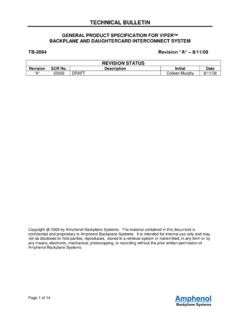
9 Can be supplied with strain relief integral with compression nut RE(SR) . RTRTRTRTRTE nvironmental applications. Supplied without rear accessories. Design provides serrations on rear threads of TypeShell StyleService Class Shell Size-Insert TypeAlternate PositionSpecial VariationsRX 1. 2. 3. 4. 5. 6. 4. Select a Shell Size & Insert Arrangement see page 6-9 Connector TypeShell StyleService ClassShell Size-Insert TypeAlternate PositionSpecial Variations22-2 1. 2. 3. 4. 5. 6. 5. Select a contact TypeDesignatesPPin ContactsSSocket ContactsConnector TypeShell StyleService ClassShell Size- Insert TypeAlternate PositionSpecial VariationsP 1. 2. 3. 4. 5. 6. 27599, Series II JT MIL-DTL - 38999 / 27599, Series I LJT First number represents Shell Size, second number is the Insert Arrangement. Not applicable to box mounting style or LJT Series I. Not applicable to box mounting to Order (Commercial)64 contact Amphenol Aerospace for more information at 800-678-0141 IIISJT 38999 PCB HD I II AquaconAccessoriesHerm/SealFiber OpticsContactsConnectorsCablesHIgH SPEED26482 Matrix 2 83723 III501526500 Pyle 22992 Class L Back- ShellsOptions OthersEMI FilterTransientCrimp RearRelease MatrixMatrix|PyleAmphenolAerospaceROTATI ONLETTERSNORMALBADCAB5 LJT REFRELATIVE POSSIBLE POSITIONOF ROTATED MASTER KEYWAY (front face of receptacle shown)ROTATIONLETTERSNORMALBADCAB10 JT REFRELATIVE POSSIBLE POSITIONOF ROTATED MASTER KEYWAY (front face of receptacle shown) A designates Alternate keying connector assembly.
10 Other basic alternate keys are B , C and D . No letter required for normal rotation (no rotation) plug with a given rotation letter will mate with a receptacle with the same rotation letter. The AB angle for a given connec tor is the same whether it contains pins or sockets. Only the master key/keyway rotates in the shell, and the minor keys are angles shown are viewed from the front face of the connec tor, a receptacle is shown below. The angles for the plug are exactly the same except the direction of rotation is opposite of that shown for the N designation is not referenced in part number, it is 6. Select an Alternate Keying PositionConnector TypeShell StyleService ClassShell Size Insert Type Alternate PositionSpecial VariationsA 1. 2. 3. 4. 5. 6. 7. Select a Strain Relief Option or Finish Variation SuffixConnector TypeShell StyleService ClassShell Size- Insert TypeAlternate PositionSpecial Variations( ) 1.