Transcription of MILROYAL SERIES - Milton Roy
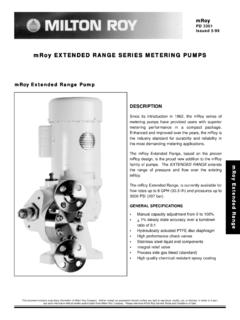
1 The MILROYAL B metering pump is a robust industrial duty metering pump for use in critical processes in oil and gas, chemical and hydrocarbon processes, water and waste treatment, and in most industries where chemical injection is MILROYAL design is modular thus allowing it to accept a variety of liquid ends and other options that perfectly tune it to process requirements. Multiplex configurations provide even greater application flexibility. General SpecificationsDrivePolar crank design - all moving parts submerged in oil. Front end scavenging - The plunger always set to top dead center on each Ends AvailableHigh Performance Diaphragm (HPD); Packed Plunger; Disc DiaphragmAccuracy over 10:1 turndown ratioMaximum Performance Ratings (per head) gph ( l/h) @ 10,000 psig (689 bar) to 626 gph (2,370 l/h) @ 75 psig (5 bar)Capacity ControlManual micrometer standard; Electronic, pneumatic, or variable speed optionalMultiplexingUp to 8 pumps driven by one motor.
2 (Limited to total of 10 HP) Consult applications engineering concerning capabilities for a specific Shipping Weight (Simplex)Approximate shipping weight is 250 600 lbs.(113 272 kg), depending on liquid end B Pumps an Accudyne Industries brandMILROYAL SERIESM etering PumpsPD 3641 Literature #PD 3641 2016 Milton Roy, LLC. All rights B Simplex with HPD Liquid End(shown with optional flanges) MILROYAL B Triplex with leak detectionan Accudyne Industries brandLiterature #PD 3641 2016 Milton Roy, LLC. All rights PERFORMANCE DIAPHRAGM (HPD) LIQUID END PERFORMANCET ypical performance based on 1725 RPM, 3 Phase*, 60 Hz motor. Derate flow rates for all other RPM 49 7 3,440 237 3,675 250 8J 70 11 1,625 112 3,215 222 3,675 250 8H 95 15 1,110 77 2,440 168 3,675 250 8G 113 18 775 53 1,905 131 3,675 250 8F 142 23 575 40 1,475 102 2,950 203 3,675 250 8K 49 14 1,730 118 2,780 189 3,675 250 8J 70 20 975 66 1,830 124 2,750 187 3,675 250 8H 95 28 650 44 1,350 92 2,030 138 3,055 208 3,675 250 8G 113 33 500 34 1,125 77 1,700 116 2,730 186 3,675 250 8F 142 11 42 375 26 900 61 1,350 92 2,400 163 3.
3 600 245 3,675 2508K 49 20 1,675 115 2,795 193 3,150 217 8J 70 28 755 52 1,515 104 2,700 186 3,150 217 8H 95 38 510 35 1,170 81 2,100 145 2,885 199 3,150 217 8G 113 46 340 23 910 63 1,755 121 2,390 165 3,150 217 8F 142 57 240 17 700 48 1,445 100 1,930 133 2,895 200 3,150 2178K 49 14 53 545 38 875 60 1,250 86 8J 70 19 72 305 21 575 40 860 59 1,250 86 8H 95 26 98 205 14 420 29 635 44 955 66 1,250 86 8G 113 31 117 160 11 355 24 535 37 850 59 1,250 86 8F 142 39 148 120 8 285 20 425 29 755 52 1,130 78 1,250 868K 49 21 79 354 24 555 38 770 53 8J 70 30 114 195 13 365 25 550 38 770 53 8H 95 40 151 130 9 270 19 405 28 610 42 770 53 8G 113 48 182 100 7 225 16 340 23 545 38 770 53 8F 142 61 231 75 5 180 12 270 19 480 33 720 50 770 538K 49 34 129 220 15 350 24 500 34 8J 70 48 182 120 8 230 16 345 24 500 34 8H 95 65 246 80 6 170 12 255 18 385 27 500 34 8G 113 77 291 60 4 140 10 215 15 340 23 500 34 8F 142 97 367 45 3 110 8 170 12 300 21 455 31 500 348K 49 52 197 140 10 225 16 300 21 8J 70
4 75 284 75 5 145 10 220 15 300 21 8H 95 101 382 50 3 105 7 160 11 245 17 300 21 8G 113 120 454 90 6 135 9 220 15 300 21 8F 142 151 572 70 5 105 7 190 13 300 21 8K 49 83 314 85 6 140 10 165 11 8J 70 119 4 50 50 3 90 6 140 10 165 11 8H 95 161 609 65 4 100 7 155 11 165 11 8G 113 191 723 55 4 85 6 1 35 9 165 11 8F 142 240 908 65 4 120 8 165 11 8K 49 170 643 70 5 100 7 8J 70 242 916 65 4 100 7 8H 95 330 1249 50 3 75 5 100 7 8G 113 391 1,480 65 4 100 7 8F 142 500 1,892 60 4 90 6 100 78K 49 216 820 50 3 75 5 8J 70 308 1,165 50 3 75 5 8H 95 419 1,585 60 4 75 5 8G 113 498 1,885 50 3 75 5 8F 142 626 2,370 45 3 70 5 75 5 GPH L/H PSIG BAR PSIG BAR PSIG BAR PSIG BAR PSIG BAR PSIG BARM axmium Discharge Pressure*2 1 2 in(64 mm)3 1 2 in(89 mm)4 in(102 mm)2 in(51 mm)1 in(38 mm)1 1 4 in(32 mm)1 in(25 mm)5/8 in(16 mm)9/16 in(14 mm)7/16 in(11 mm)
5 PlungerDiameterGearRatioCodeSPM@1725 RPMM aximumCapacity*1/3 HP( kW)1/2 HP( kW)3/4 HP( kW)1 HP( kW)1 1/2 HP( kW)2 HP( kW)Capacities listed are for discharge pressures up to 200 PSIG (14 Bar).Capacity will decrease for each 100 PSIG (7 Bar) over 200 PSIG (14 Bar).NOTES: * For single phase motors, increase horsepower by one size example: increase hp ( ) to hp ( ). Plastic liquid ends are limited to 150 PSIG (10 Bar) @ 68 F (20 C) and are linearly derated to 65 PSIG (4 Bar) @ 140 F (60 C). Derate capacity by 5% when applying a diaphragm rupture detection Accudyne Industries brandLiterature #PD 3641 2016 Milton Roy, LLC. All rights LIQUID END DIMENSIONSMAXIMUM ALLOWABLE SUCTION PRESSURE RANGE HPDN otes:* Dimensions shown are for single diaphragm liquid ends.
6 Contact factory for double diaphragm dimensions. A & B dimensions are based on standard ball check configuration: Consult factory for dimensions on optional configurations. Suction and discharge connections are horizontal in metal and vertical in plastic except on plastic 3 in (89 mm) plunger & 4 in (102 mm) plunger, where suction is horizontal, discharge is vertical and dimension C for discharge is 1013 16 in (275 mm). in. mm in. mm in. mm in. mm in. 7 16 11 55 8 121 55 8 121 4 102 9 16 14 55 8 121 55 8 121 4 102 5 8 16 55 8 121 55 8 121 4 102 1 25 4 13 16 122 4 13 16 122 6 1 8 156 1 32 57 32 133 57 32 133 6 1 8 156 1 38 71 16 179 71 16 179 8 1 4 210 1 2 51 7 9 16 192 7 9 16 192 8 1 4 210 1 2 64 7 9 16 192 7 9 16 192 8 1 4 210 1 3 89 101 8 257 10 1 8 257 13 330 1 4 102 101 8 257 10 1 8 257 13 330 1 1 25 6 165 6 165 615 1 176 1 32 6 165 6 165 615 16 176 1 38 9 9 16 243 9 9 16 243 8 222 1 2 51 9 9 16 243 9 9 16 243 8 222 1 2 64 9 9 16 243 9 9 16 243 8 222 1 3 89 16 406 13 330 13 337 1
7 4 102 16 406 13 330 13 337 1 in. mm PSIG Bar PSIG Bar PSIG Bar 7 16 11 660 46 1,130 77 1,450 98 9 16 14 460 31 770 53 985 68 5 8 16 360 25 590 40 750 51 1 25 100 7 1 32 100 7 1 38 85 6 100 7 2 51 60 4 85 6 100 7 2 64 45 3 60 4 70 5 3 89 20 35 2 40 3 4 100 15 1 25 30 2 Plunger Diameter Standard Mid Range High Range MaterialMetal(Double Ball)StandardMetal(Single Ball)StandardPlastic(Double Ball)StandardPlungerDiameterA B C*DFor exact dimensions, request a certified drawingan Accudyne Industries brandLiterature #PD 3641 2016 Milton Roy, LLC.
8 All rights PERFORMANCE DIAPHRAGM (HPD) LIQUID END MODEL CODE Plunger = 7 16 in09 = 9 16 in10 = 5 8 in16 = 1 in20 = 1 1 4 in24 = 1 in32 = 2 in40 = 2 in56 = 3 in64 = 4 inEnd Item Model CodeMBHO ption Select Number Suction Pressure Range**ST = StandardH2 = MediumH3 = High Ball Quantity 11 = Single22 = Double Base11 = Simplex22 = Duplex33 = Simplex44 = Quadruplex NN = NoneConnections SE = NPTT1 = ANSI 150 lb. threadedT3 = ANSI 300 lb. threadedT6 = ANSI 600 lb. threadedS1 = ANSI 150 lb. socket weldS3 = ANSI 300 lb. socket weldS6 = ANSI 600 lb. socket weldS9 = ANSI 1,500 lb. socket weldRupture Detection/Double = NoneC5 = Rupt. Det. w/gauge SN = Rupt.
9 Det. w/gauge & Nema 4 switch SE = Rupt. Det. w/gauge & exp. pr. switch DD = Double DiaphragmDP = Double Diaphragm w/Probe HT = High Temp Diaphragm no rupt detect (190 to 250 degree F max.)DH = High Temp Double DiaphragmxxxCapacity Adjustment ManualM4 = Micrometer (304 SS)Electronic, 4 20 mA InputE1 = Nema 4, 115 VE2 = Nema 4, 230 VEA = Explosion Proof, 115 VEB = Explosion Proof, 230 V PneumaticPN = 3-15 PSI Motor MountAA = None Flange MountCB = Nema 56 CCC = Nema 143TC, 145 TCCD = Nema 182TC, 184 TCCE = Nema 213TC, 215TC Metric Mount, B5 FlangeMD = 1EC 80ME = 1EC 90MF = 1EC 100/112 Foot MountFJ = Nema 56FK = Nema 143 TFL = Nema 145 TFN = Nema 182T, 184T Operating Pressure PB = 30-220 psig (250 max.)
10 RV)PC = 221-450 psig (515 max. RV)PD = 451-750 psig (860 max. RV)PE = 751-1,250 psig (1,435 max. RV)PF = 1,251-3,675 psig (4,025 max. RV) Liquid End Material 1 = 316 SS 2 = Plastic 5 = Alloy 20 6 = Alloy C22 Gear/ShaftSingle Shaft8F = :18G = :18H = :18J = 25:18K = 36:18M = :1xxxxDouble Shaft8A = :18B = :18C = :18D = 25:18E = 36:18L = :1xxxx-NOTES: Operating pressure is the pressure of the applications system. The internal relief valve is normally set 15% above the operating pressure. If an internal relief valve setting greater than 15% above the operating pressure range is required, select the operating pressure that will accommodate the relief valve setting. Flange sizes equal the NPT connection size as noted on the liquid end drawing.