Transcription of Mini MB Ticket Printer - Boca Systems
1 Users Manual mini MB Ticket PrinterMini MB Ticket PrinterBOCA Systems ,INC. 1996 Boca Systems , rights the copyright laws, this manual may not be copied, in whole or in part, withoutthe written consent of effort has been made to ensure that the information in this manual is is not responsible for printing or clerical errors and reserves the right to changespecifications without of the tour of your Interface Paper - Theory and and Parts Guide18-19 Table of Figures and AppendicesPageFigure 1 Packaging2 Figure 2 mini MB Ticket Printer 3 Figure 3aMini MB side view4 Figure 3bMini MB side view - Electronics Cover Removed4 Figure 4 Rear view5 Figure 5 Side view with electronics exposed5 Figure 6 Ticket loading6 Figure 7 Slider Adjustment7 Figure 8 Optical Devices11 Figure 9 Print head removal13 Appendix AOperator Menu options through control panelAppendix BFGL Printer Comparison ChartFCC NOTICENOTE.
2 The equipment has been tested and found to comply with the limits for a classA digital device, pursuant to part 15 of the FCC limits are designed toprovide reasonable protection against harmful interference when the equipment isoperated in a commercial equipment generates, uses, and can radi-ate radio frequency energy and , if not installed and used in accordance with theinstruction manual, may cause harmful interference to radio of this equipment in a residential area is likely to cause harmful interferencein which case the user will be required to correct the interference at his own is subject to the following two device may not cause harmful interference, device must accept any interference received, including interference that may cause undesired :This unit was tested with shielded cables on the peripheral must be used with the unit to insure INFORMATIONPRINTERS - BOCA warrants each Printer to be free of defects for a period of one yearfrom the date of shipment when subject to normal use and warranty cov-ers all parts and labor except for the print head which is warranted for 90 labor is to be performed at the BOCA damaged by misuseor negligence including damage to print heads caused by defective Ticket stock isexcluded from this defective equipment meeting these conditions should be returned to BOCA forrepair (freight prepaid)
3 In its original box and packing short note describingthe failure should be enclosed with the damaged in shipping should be reported immediately both to BOCA and tothe WARRANTY PLAN - BOCA offers extended warranty plans for all plans cover all parts and labor is to be performed at theBOCA damaged by misuse or negligence including damage to printheads caused by defective Ticket stock is excluded from this extended , at his option, may request BOCA to ship individual parts to expedite simplerepair certain cases where the customer is unable to wait for the nor-mal repair cycle, BOCA will ship an exchange Printer within one business day afternotification by the freight charges are the responsibility of the IntroductionThe BOCA mini MB is a direct thermal Ticket Printer with an integrated cutting mecha-nism designed for point of sale ticketing manual will provide theuser with general information regarding Printer set-up, configuration and review your programming guide for additional Unpacking the PrinterThe Printer is shipped in a ruggedized save packing material forfuture the Printer (see figure 1) and accessories from the box andinspect for obvious damage is noticed, please report it immediately :(561) 998-9600 Fax:(561) 998-9609 The following items should be in the box.
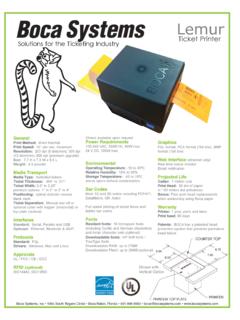
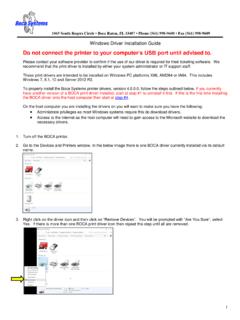
4 A) Ticket Printerb) Hopper c) AC power cord d) Interface cable (optional) e) Programming guidef) This manual2 Figure 1 - A Tour of Your PrinterFigure 2- mini MB Ticket printerHopperControl PanelLCD3ON/OFF SwitchFigure 3a- mini MB side viewCutter AssemblyOptical detectorsElectronics Cover (partially obscured)Figure 3b- mini MB side viewElectronics Cover RemovedPower Supply BoardLogic Board4 Figure 4- mini MB rear viewFigure 5- mini MB side view Voltage Selector Feed tickets hereInterface ConnectorAC Power Connector5 Fuse Holder (2amp,SB)Electronics mounting plateToroid TransformerStepper InstallationThe mini MB Ticket Printer is designed to be mounted on a counter top or , prior to site preparation and installation, the Printer should be powered upand run in the self test the Printer flat on a counter as shown in figure 3 Awith the cover the rear cover and verify that the voltage selector isproperly set for your line voltage (110/220v) as shown in figure the AC cordand interface cable into the proper connectors as shown infigure power on(figure 2) and you will hear the cutter motor LCD will display PAPER loading tickets through the entrance slot (figure 4) with a smooth motion untilthe Printer automatically positions the.
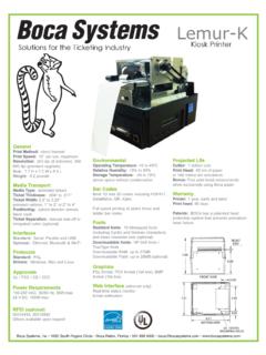
5 Tickets should be loaded with the black mark facing typical ticketformats and feed directions are shown below (figure 6).After the Ticket is automatically positioned (the READYLED will be illuminated), pressthe TEST button located on the control panel (figure 2) to print a test thatthe Printer properly works with your system by issuing a Ticket through your may now install the Printer in its permanent room should beprovided behind the Printer for the smooth feeding of do not prevent theticket hopper from operating by touching tickets during the printing Mark on Underside Mark on Underside ofTicket6 Figure 6- Ticket ConfigurationThe mini MB is factory configured for a variety of customer printeris available in a standard FGL20 electronics package or with an enhanced resolution is 200dpi and 300 dpi is available as an see Appendix Bfor the comparison of FGL 20 and Printer is available in a number of fixed Ticket widths or with an optional adjustablepaper path (see figure 7).
6 The Printer is factory configured for either serial or parallelinterface (see pinouts in section ).A number of other features including baud rate, cut count and print speed are also fac-tory set but can be modified (Operator Menu) through the touch panel as described inAppendix users will never have reason to change the options in the Adjustment for adjustable paper path stock into the paper thumb screws on slider towards the stock until it touches slider away from the stock a little (1/32 ) thumb screwsCAUTION:Do not adjust slider tight against will cause a feed stock will move from side to side ifthe slider is adjusted too far away fromthe the Ticket ScrewsFigure 7- Slider Standard Interface Serial PinoutsRS232 (Standard)RS232 (PC type)PinFunctionPinFunction2 Printer Transmit2 Printer Receive3 Printer Receive3 Printer Transmit7 Ground5 RTS (+5 Vdc)5,20 DTR ( Printer Ready)6 DTR ( Printer Ready)4,22 RTS (+5 Vdc)7 Ground8 CD (+5 Vdc) Typical RS232 Pin Connections* Optional Parallel PinoutPinFunction1 Strobe (negative)2-9 Data (DB0-BD7)10 ACK (negative)11 BUSY12 PAPER OUT15 ERROR (negative)18 GroundNOTE:The above pinouts may vary on certain printers due to special customerrequest.
7 (Standard)25 PIN PCBOCA CPU23 RXD33 TXD77 GND206 DSR205 CTS*208 CD*(Standard)9 PIN PCBOCA CPU22 RXD33 TXD75 GND206 DSR201 CD*208 CTS*(PC Type)25 PIN PCBOCA CPU22 TXD33 RXD55 CTS*66 DSR77 GND88 CD*(PC Type)9 PIN PCBOCA CPU23 TXD32 RXD58 CTS*66 DSR75 GND81 CD* Thermal Paper - Theory & SpecificationThe print head s life expectancy is composed of both a mechanical and an electrical ofthese factors are strongly influenced by the quality of the thermal paper print head has a theoretical rating of 60 number is based upon the assumption thatthe head will be used with a good quality, top coated thermal and poorly top coatedthermal papers are abrasive to the print head and have been found to wear through the head after lessthan one factors which may contribute to premature mechanical wear are the use of non-thermal inks andstray metallic particles stuck in Ticket inks colors such as opaque white (which con-tains titanium dioxide)
8 Are also highly , there are no available devices for quantitatively measuring the abrasiveness of a , we have developed a slightly subjective, but effective method of weeding out overlyabrasive Ticket heat element, dot, on the print head has a theoretical life expectancy of 100 million is based on the assumption that each activation will cause the dot temperature to approach thedot s maximum recommended at lower temperatures will increase the theoreticallife expectancy, while slight temperature increases will seriously (exponentially) degrade the head thermal paper can affect the electrical head life in two , slow to image papers, willtypically encourage the user to increase the voltage to darken the printed will directlyincrease the head temperature resulting in reduced head , the higher temperatures willfrequently cause the ink to peel off the Ticket and deposit onto the print ink debris will disruptthe normal transfer of heat from the head to the further increases the head temperatureabove the desired use of non-thermal inks and/or non-top coated papers also will cause theink to release and deposit on the print upon the above technical information.
9 BOCA has always tried to encourage our customers to usethe proper thermal papers to maximize the life of their print provides an extensive seriesof papers which meet the above criteria for low abrasion and high have also tested andapproved a number of Ricoh thermal papers which meet our we have not had the oppor-tunity to test other manufacturers thermal papers, we feel confident that other papers manufactured withthe above goals in mind should be acceptable for use in our following list of papers havebeen approved by and 200 dpi usageBOCATLD7, TLD7R, TLD5, SF7, P8 Ricoh120 TLD, 120 LCSB, 120LD300 dpi usageBOCAHS7, SFHS7 Ricoh150 TLAP lease note that the 300 dpi papers may be used on 100 and 200 dpi fact, doing so willincrease the electrical life of the head as this will allow the head to operate at a lower use 300 dpi heads with 200 dpi Maintenance and AdjustmentsYour Ticket Printer is solidly constructed and has been designed for high volume minimal care to provide maximum section provides an overview of Printer maintenance, including part alignments,adjustment and discussion purposes, the Printer consists of three major modules or assemblies.
10 Paper guide and print head assembly Cutter assembly Logic board assemblyAs a safety precaution,all service to the Printer should be done with power offand the AC cord unplugged from the Paper Guide and Print Head AssemblyThe principal function of this assembly is to guide the Ticket stock to the thermal printhead where thermal printing takes , this assembly houses the driveplaten and optical necessary, the total assembly can be removed from , all replacements and adjustments of the components of this assemblycan be done without removing the total most common adjustments andreplacements regarding this assembly Optical Devices (see figure 8)There are two identical opto devices mounted on a black aluminum bracket beneaththe paper opto on the left controls automatic Ticket loading and the opto onthe right controls cut or adjustment of either opto should bedone without removing the bracket from the paper opto position is factory set and adjustment should not be.