Transcription of Mode AV-1-300 Aar Chec alve 300 s 20, ar) 2-1/2 nc DN65 ...
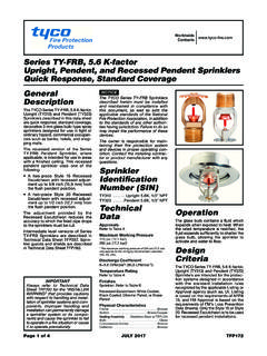
1 Model AV-1-300 Alarm Check Valve, 300 psi (20,7 bar) 2-1/2 , 4, 6 & 8 Inch (DN65, DN100, DN150 & DN200) Vertical or Horizontal* InstallationPage 1 of 20 MARCH 2020 TFP910 Worldwide to Technical Data Sheet TFP2300 for warnings pertaining to regulatory and health DescriptionThe TYCO Model AV-1-300 Alarm Check Valves are divided seat ring, rubber-faced clapper, waterflow alarm check valves that are intended for use in wet pipe (automatic sprinkler) fire protection systems. They may be installed vertically or horizontally*, and they are designed to automati-cally actuate electric and/or hydraulic alarms when there is a steady flow of water into the system that is equivalent to the discharge rate of one or more separately ordered Model RC-1 Retard Chamber (Ref.)
2 Technical Data Sheet TFP920) is required for installa-tions subject to variable pressures. It is used to help prevent false alarms asso-ciated with pressure variations in public water AV-1-300 Alarm Check Valve Trim includes pressure gauges to monitor system pressure conditions, a bypass check valve, a main drain valve, and an alarm test valve. The bypass check valve reduces the possibility of false alarms by permitting slow as well as small transient increases in water supply pressure to be passed through to the system without opening the waterway TYCO Model AV-1-300 Alarm Check Valves described herein must be installed and maintained in compliance with this document, as well as with the applicable standards of the NATIONAL FIRE PROTECTION ASSOCIATION (NFPA), in addition to the standards of any authorities having jurisdiction.
3 Failure to do so may impair the integ-rity of these owner is responsible for main-taining their fire protection system and devices in proper operating con-dition. Contact the installing contrac-tor or product manufacturer with any DataApprovalsUL and C-UL Listed FM ApprovedWorking Water Pressure Range20 to 300 psi (1,4 to 20,7 bar)Friction LossRefer to Graph ConnectionsGroove x Groove Flange x Groove Flange x Flange Refer to Table A for size applicabilityWeightsRefer to Table CharacteristicsThe body is ductile iron, the hand-hole cover is ductile iron, and the seat ring is bronze. The clapper for the 2-1/2 in. (DN65) valve size is stainless steel. The clapper for the larger valve sizes is ductile iron.
4 All valve sizes utilize an EPDM clapper connections are available drilled per ANSI, ISO, AS, and JIS specifications as detailed in Table port connections for the AV-1-300 Valves are available NPT threaded or threaded per ISO 7-1 as detailed in the Ordering Procedure section. Valves with NPT threaded ports will readily accept the trim arrangements detailed in Figures 4 through 6.* 4, 6, and 8 inch (DN100, DN150, and DN200) valve sizes TFP910 Page 2 of 20 Nominal Valve Size Inches (DN)Groove x Groove lb (kg)Flange x Groove lb (kg)Flange x Flange lb (kg) 2-1/2 (65)22 (10,0)28 (12,7)N/A4 (100)38 (17, 2 )47 (21,3)57 (25,9)6 (150)58 (26,3)70 (31,8)84 ( 3 8 ,1)8 (200)102 (46,3)120 (54,4)149 ( 6 7, 6 ).
5 (a)(b) CoverValve (a)Handhole CoverGasketSee (a) or (b)Clapper FacingClapper WasherVALVE PARTSSeat RingNRSee (b)Lock Nut, 2-1/2 Inch ValveSee (b)Self-Locking HexCap Screw, 4, 6, & 8 Inch ValvesSee (b)REPLACEMENT PARTSDESCRIPTIONP/N92-200-1-41692-200-1- 62092-200-1-81692-200-1-21692-200-1-218 See (b)Clapper Hinge PinClapper HingeSee (b)Clapper SpringPin Bushing, 2-1/2 Inch ValveNRValves4, 6, & 8 InchNRClapperSee (b)92-200-1-42392-200-1-62392-200-1-823 Hex Bolt,Handhole Cover2-1/2 Inch Valve,x 1-1/4" PARTS1/2-13 UNC-2A6 Inch Valve,x 1-3/4" LongCH1/2-13 UNC-2A8 Inch Valve,x 2" LongCH3/4-10 UNC-2A4, 6, & 8 InchPlug, 3/8" NPT,Valves onlyCHSquare Head PipeClapper Hinge Pin4 Inch Valve,x 1-3/4" LongCH1/2-13 UNC-2 ARepair Parts Kit,Includes 3 & 64 Inch Valve6 Inch ValveClapper Assembly,Includes 5-9, 114 Inch Valve6 Inch Valve8 Inch Valve8 Inch Valve2-1/2 Inch Valve2-1/2 Inch ValveIncludes 5-11F x F valve shown for reference.
6 Components for G x G and F x :valves are : Not ReplaceableCH: Common INCHVALVECLAPPERASSEMBLY4, 6, & 8 INCHVALVESFIGURE 1 MODEL AV-1-300 ALARM CHECK VALVE AS S E M B LYTABLE A MODEL AV-1-300 ALARM CHECK VALVE AVAILABLE VALVE END CONNECTIONS AND VALVE WEIGHTSTFP910 Page 3 of 206 INCH (DN150)4 INCH (DN100) 2-1/2 INCH (DN65)8 INCH (DN200)6004001000 FLOW RATE IN LITRES PER MINUTE (LPM)(1 GPM = 3,785 LPM)FLOW RATE IN GALLONS PER MINUTE (GPM) PRESSURE DROPIN POUNDS PER SQUARE INCH (PSI) PRESSURE DROP IN BAR(1 PSI = 0,06895 BAR)0,0630007001000200040000,050,080,070 ,090,100,2010000500030007000150002001002 32311 Same drilling as for BS 4504 Section (PN16) and DIN 2532 (PN16). (190,5) (241,3) (19,0) (22,2) (178,0) (235,0) (18,0) (22,0) (175,0) (23,0) (19,0) (240,0) (298,5) (22,2) (292,0) (22,0) (295,0) (23,0) (290,0) (139,7) (19,0) (127,0) (140,0) (22,0) (18,0) (18,0) (22,0) (22,0) (18,0) (19,0)4 Inch(DN100)6 Inch(DN150)8 Inch(DN200) 2-1/2 Inch(DN65) (180,0) (240,0) (295,0) (145,0) drilling as for BS 4504 Section (PN10) and DIN 2532 (PN10).
7 Dim. ABolt CircleDiameterDim. BBolt HoleDiameterQty. NNumber ofBolt HolesNominalValveSizeSame drilling as for (Class 150) and (Class 250).ANSI (Class 125)AS 2129(Table E)ISO 2084(PN10)JIS B 2210(10K)Flange Drilling Speci cationNominal Dimensions in Inches and (mm)ISO 2084(PN16)USEISO 2084(PN16)GRAPH A MODEL AV-1-300 ALARM CHECK VALVE NOMINAL PRESSURE LOSS VERSUS FLOWTABLE B MODEL AV-1-300 ALARM CHECK VALVE FLANGE DRILLING SPECIFICATIONSTFP910 Page 4 of 20 OperationWhen the fire protection system is initially pressurized, water flows into the system until the water supply and system pressure become equalized, and the torsion Spring closes the Waterway Clapper in the Alarm Check Valve. Once the pressures stabilize, the Alarm Check Valve is in service and the centrally located groove in the Seat Ring is sealed.
8 Consequently, with the Alarm Check Valve set for service, there is no flow through the alarm port to the alarm devices ( , water motor alarm and/or pressure alarm switch).When there is a steady flow of water into the sprinkler system due to a sprin-kler operation, the Waterway Clapper opens as shown in Figure 2. Water is then permitted to flow into the cen-trally located groove in the Seat Ring and out through the alarm port towards the Restriction Assembly as shown in Figure 3. When the flow through the Inlet Restriction of the Restriction Assembly exceeds the flow through the Outlet Restriction, the Retard Chamber (where provided for systems with vari-able pressure), begins to , the Water Motor Alarm and/or the pressure alarm switch will be actuated.
9 The alarms will continue to be actuated as long as the Water-way Clapper remains open. Water in the alarm lines will automatically drain out through the 1/8 inch (3,2 mm) Drain Orifice in the Restriction Assembly (see Figure 3) when the Waterway Clapper closes (due to a stop in the flow of water into the sprinkler system).For variable pressure systems, slow as well as small transient increases in water supply pressure may continue to build up in the system (via the Bypass Check Valve) without opening the Waterway transient surge in supply pres-sure that is sufficient only to open the Waterway Clapper momentarily will not cause a false alarm, and a portion of the increase in pressure will be trapped within the system, thus reducing the possibility of another opening.
10 Any water in the alarm line is automatically drained, further reducing the possibil-ity of a false alarm due to a successive transient surge in supply CriteriaIn planning installation of the TYCO Model AV-1-300 Alarm Check Valves, consideration must be given to the dis-posal of the large quantities of water that may be associated with draining the system or performing a flow installed in the vertical position must have the flow going up. Valves installed in the horizontal position must be positioned so that the drain connec-tion points sprinkler system designer must be aware that the configuration of the piping network and its tendency to trap pockets of air (such as in the case of a peaked-roof gridded system) can affect the performance of the alarm system.