Transcription of Model 2511A TESTa n DRaIn
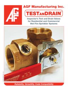
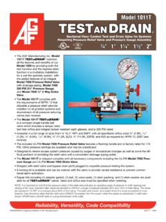
1 Model 2511 ATESTa nDRaIn 1" 1 " 2"Sectional Floor Control Test and DRaIn Valve for Systems Requiring Pressure Relief ValveReliability, Versatility, Code Compatibility The AGF Manufacturing Inc. Model 2511A TESTa nDRaIn matches all the features and benefits of our Model 2500 by providing both the test function and the express DRaIn function in a multistory installation for a wet fire sprinkler system, with the added feature of an integral Model 7000 Pressure Relief Valve with DRaIn -age piping. The 2" Model 2511A features a groove x groove connection. The Model 2511A complies with the require-ments of NFPA-13 that stipulate a pressure relief valve be installed on all gridded systems and downstream of all pressure reducing valves (see reverse). The Model 2511A TESTa nDRaIn is a multi-direction, compact single handle ball valve which includes a tamper resistant test orifice and integral tamper resistant sight glasses, and is 300 PSI rated.
2 The Model 2511A TESTa nDRaIn provides an alternate handle location from the Model 1011A for difficult install situations Available in 1" and 1 " NPT and 2" Groove, with all specifiable orifice sizes 8" ( ), 7 16" ( ), " ( ), 17 32" ( ), 5 8" ( , ELO), " ( , ESFR) and K25 as required by NFPA 13, 2007 Edition (see reverse). The included UL/FM Model 7000 Pressure Relief Valve features a flushing handle and is factory rated at 175 PSI. Other pressure settings are available and may be substituted. Designed to relieve excess system pressure caused by surges or temperature changes as well as solve the dif-ficult problem of providing the relief valve with a convenient drainage-piping outlet. Shipped with relief valve and bypass DRaIn ports plugged to expedite pressure testing the system.
3 A locking kit is available and can be ordered with the valve to provide vandal resistance or prevent uninten-tional alarm activation. Repair kits including (1) adapter gasket, (1) ball, (2) valve seats, (1) stem packing, and (1) stem washer are avail-able for all TESTa nDRaIn valves. Valve and orifice size must be specified when : It is important to note that the pressure rating of the relief valve indicates an operating range of pressure for both opening and closing of the valve. Standard relief valves are required to oPeN in a range of pressure between 90% and 105% of their rating. the valves are required to CLoSe at a pressure above 80% of that rating. the relief valve should be installed where it is easily accessible for main-tenance. Care should be taken that the relief valve CANNot be isolated from the system when the system is operational.
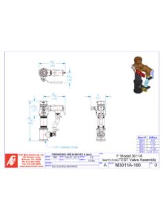
4 A relief valve should NeVeR have a shutoff valve or a plug downstream of its 10/09 TESTANDRAIN is a registered trademark of AGF Manufacturing 2511 ATESTa nDRaIn RELIEF VALV EDRAINACDBINLETAEFGHDRAINRELIEF VALV EINLETAp p r o vA l sUL and ULC Listed: (EX4019 & EX4533)FM Approved NYC-BSA No. 720-87-SMJob Name:_____Architect: _____Engineer: _____Contractor: _____USA Patent # 4741361 and Other Patents PendingMA t e r iA l sHandle: SteelStem: Rod BrassBall: BrassBody: BronzeValve Seat: Impregnated Teflon Indicator Plate: SteelRelief Valve: BronzeBypass Fittings: BrassBypass Tubing: NylobraidMo d e l 2511A - pl A n vi e wMo d e l 2511A - dr A i n t o ri g h tAGF Manufacturing Quaker Lane, Malvern, PA 19355 Phone: 610-240-4900 Fax: 2511A 300 PSI Bronze Ball Valve, Model 7000 Pressure Relief Valve Factory Rated at 175 PSI with other settings availabledi M e n s i o n sOrifice Size Available.
5 3 8", 7 16", 1 2", 17 32", ELO (5 8"), ESFR (3 4")*, K25**SIZEABCDEFGH1"83 4"(222 mm)21 4"(57 mm)11 4"(32 mm)31 2"(89 mm)33 8"(86 mm)113 16"(44 mm)25 8"(67 mm)41 4"(108 mm)11 4"101 16"(256 mm)21 2"(64 mm)13 8"(35 mm)37 8"(98 mm)33 8"(86 mm)21 8"(54 mm)31 16"(78 mm)43 4"(121 mm)2" 123 4"(324 mm)3"(76 mm)113 16"(46 mm)413 16"(122 mm)55 8"(143 mm)25 8"(67 mm)33 4"(95 mm)57 8"(149 mm)* Available on 11 4" to 2" size units only** Available on 2" size units only 2" M2500 is Groove x Groove onlyth e Mo d e l 2511A p r o v i d e s A l l o f t h e f o l l o w i n the 2007 Edition of NFPA 13 Chapter * Provisions shall be made to properly DRaIn all parts of the DRaIn connections, interior sectional or floor control valve(s) shall be provided with a DRaIn connection having a minimum size as shown in Table Drains shall discharge outside or to a DRaIn capable of handling the flow of the (Wet Pipe System) test connection is permitted to terminate into a DRaIn capable of accepting full using an approved sight test connection containing a smooth bore corrosion-resistant orifice giving a flow equivalent to one The test connection valve shall be readily shall be permitted to be installed in any downstream of the waterflow (Dry Pipe System)
6 A trip test connection not less than 1" in diameter, terminating in a smooth bore corrosion-resistant orifice, to provide a flow equivalent to one The trip test with a shutoff valve and plug not less than 1", at least one of which shall be - a gridded wet pipe system shall be provided with a relief valve set to operate at 175 PSI or 10 PSI in excess of the maximum system pressure, whichever is * A relief valve of not less than " in size shall be provided on the discharge side of the pressure-reducing valve set to operate at a pressure not exceeding 175 - consideration should be given to piping the discharge from the (pressure relief) valve&