Transcription of Model DE Electronically Controlled Diesel Fuel …
1 Model DE Electronically Controlled Diesel Fuel injection PumpOperation and Instruction Manual CONTENTSGENERALA. Purpose of the ManualB. Model Number SystemC. General InformationSECTION 1 CONSTRUCTION AND OPERATIONA. Components and FunctionB. Electrical CircuitryC. Fuel FlowD. Transfer PumpE. Transfer Pump RegulatorF. ChargingG. Discharging, Spill-Pump-SpillH. Snubber PlatesI. Return Fuel CircuitJ. Dynamic Pump TimingSECTION 2 DISASSEMBLYSECTION 3 CLEANING AND PARTS INSPECTIONA. Component InspectionB. Poppet Valve ShimsC. Supplementary InspectionSECTION 4 REASSEMBLYSECTION 5 TEST BENCH REQUIREMENTS ANDPROCEDURESA. Special Test Equipment RequirementsB. Test Bench SetupSECTION 6 GENERAL ValuesB. Exploded ViewiiiGENERALA. Purpose Of The ManualThis manual is expressly intended to pro-vide qualified, trained Diesel fuel injectiontechnicians the information necessary todisassemble, reassemble and prepare totest the Stanadyne DE electronic Diesel fuelinjection pump.
2 In addition to this manualall special tools and test equipment as out-lined herein are needed plus all servicepertinent literature, the individual pumpspecification containing the calibration in-formation and a parts manual is not intended to be used byuntrained, inexperienced persons to at-tempt to service the product. Such unau-thorized service could result in violationsof emission regulations, pump damage orpossibly even engine damage. No serviceshould be performed on the DE pump be-fore studying this manual and becomingfamiliar with the principles and instructionswhich Model Number SystemThe following information appears on theDE pump Date Code reference Service Bulle-tin 4392. Model Number See description thatfollows3. Assembly Plant (J = Jacksonville, NorthCarolina4. Serial Number5. Customer Part NumberThe Model number describes the DE pumpas follows: abc d eDE24355780a.)
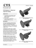
3 DE = D series pump, E electronicb. 2 = two pumping plungersc. 4 = number of cylinders servedd. 35 = abbreviation of the pumpingplunger diameter. In this case - .350inche. 5780 = specification number. Deter-mines the selection of parts and adjust-ments for a given application. Must beincluded in any reference to the pumpC. General InformationThe Model DE pump is described as anopposed plunger, rotary distributor, elec-tronically Controlled , spill solenoid type ofpump. When the spill-pump-spill controlstrategy is employed by the equipment sElectronic Control Unit (ECU), the pumpcan be described as a variable beginningand ending of injection 507968 SECTION 1 - CONSTRUCTION AND OPERATIONM odel DE ElectronicFuel injection PumpA. Components and Functions ( )The main components of the DE pump arepictured above in Figure They include:1.
4 Fuel Inlet Fitting2. Return Line Connector/HousingPressure Regulator3. Heavy Duty Drive Shaft4. Transfer Pump5. Cam Ring6. Distributor Rotor7. Poppet Valve8. Fuel Control Solenoid9. Discharge Fittings with SnubberComponentsIThe main rotating components are the driveshaft, the cam roller shoes and cam rollers,transfer pump blades and their retainer, and thedistributor rotor and poppet the DE pump Shown in Figure , the driveshaft is supported at both ends by needle bear-ings and carries the two cam roller shoes andcam rollers. It also incorporates a slot, whichengages with a tang on the distributor rotor todrive the latter. As the drive shaft is rotated, in-ternal lobes on the cam ring drive the cam roll-ers and shoes inward, simultaneously displac-ing the two opposed pumping plungers carriedin the rotor.
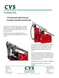
5 The number of cam lobes equalsthe number of engine cylinders being . distributor rotor in the 4-cylinder design ofthe DE pump incorporates no charging portswhereas the six cylinder design incorporatesone. Both designs incorporate one dischargeport. In the four-cylinder pump all charging fuelmust pass around the poppet valve that re-Fig. (1 PULSE/CYL)ELECTRONICCONTROL UNITINJECTPULSER eturn Fuel TemperatureMANIFOLDABSOLUTEPRESSUREENGIN ECOOLANTTEMPERATURECRANKSHAFTREFERENCE(1 PULSE/CYL)MANIFOLDABSOLUTEPRESSUREENGINE COOLANTTEMPERATURECRANKSHAFTREFERENCE(1 PULSE/CYL)ELECTRONICCONTROL UNITINJECTPULSEELECTRONICCONTROL UNITINJECTPULSER eturn Fuel Temperaturemains open during the charging phase of thepump sequenceThe DE hydraulic head assembly contains thebore in which the rotor revolves, and the charg-ing and discharge ports, a high-pressure ac-cumulator to absorb the pressure spikes fromthe fuel spilling event and alow-pressure accumulator toassist with rotor charging athigh speeds.
6 The head also in-corporates discharge fittingseach of which contains a snub-ber plate, snubber seat, snub-ber spring and retaining snubber plates are de-signed to control the injectionpressure following and betweeneach injection to prevent sec-ondary injections or other unde-sirable injection line Electrical Circuitry (Figure and )The DE pump only incorporates one sensor, athermistor that provides the Engine ControlModule (ECM) with fuel temperature OEM s equipment ECM switches currentDE-10 PumpFig. the pump solenoid on and off. On the earlypart of the pumping cam ramp the solenoid, inmost situations, will remain un-energized allow-ing the plunger displaced volume to be a precise moment in the discharge se-quence the ECM energizes the solenoid mov-ing the armature pin in contact with the rotormounted poppet valve causing the valve to seatand seal.
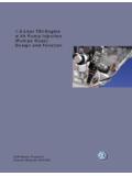
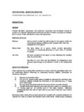
7 When the poppet valve seals, injec-tion pumping commences. When the ECM pro-gram determines that the engine has receivedthe correct amount of fuel, the current to thesolenoid is interrupted allowing the poppet valveto unseat spilling the remainder of the fuelcharge. Hence the DE pump has a spill-pump-spill fueling ControlModule12345671. Armature Pin2. Poppet Valve3. Solenoid Terminal (2)4. Solenoid Armature CoverRetainer6. Adjustable SpacerRetainer7. Adjustable Spacer(Crush Washer)Fig Fuel TemperatureCrankshaftReference (1pulse/CYL)EngineCoolantTemperatureMani foldAbsolutePressureInjectPulseLube OilInjection PressureHousing PressureTransfer PumpPressureC. Fuel Flow (Figures and )If so equipped, fuel is drawn from the tank bya mechanical or electriclift pump and flowsthrough a fuel filter andwater separator andthen to the inlet of the in-jection pump.
8 The liftpump produces a posi-tive pressure, but ofmore importance, asolid column of fuel atthe inlet of the fuel then flows intothe vane type transferpump where it is pres-surized from 0 to ap-proximately 160 psi de-pending on fuel then flows from a transferpump porting screw through a passage onthe side of the housing, through the head lock-ing screw to a passage through the hydraulichead to the spill chamber. ( pumps with charg-ing ports also direct this fuel to the chargingannulus in the hydraulic head.) Located be-tween the head locking screw and the spillchamber is a passage way that allows fuelpressure to act on the charging DE pump has no built-in governor. Gover-nor regulation, high and low idle speeds, throttleprogression and injection timing are all sensedand Controlled by the ECM hardware and soft-ware.
9 injection pump adjustments are limited totransfer pump pressure and return oil quantity .Fig. high speeds the charging accumulatoradds its volume of fuel to the volume oftransfer pump supplied fuel insuring com-plete pumping plunger hydraulic head also contains a pas-sage, which connects transfer pump pres-sure to the interior of the housing. Locatedin this passage is a vent wire assemblywhich permits a small flow of fuel to bevented into the housing as well as purgingany air entrained in the fuel. From the hous-ing the air can be vented from the pumpvia the return line connector/housing pres-sure regulator and returned to the fuel flow of return oil to the fuel tank alsoserves to carry the heat from the pump dur-ing not used for injection and not inter-nally leaked into the housing flowsthrough a return passage in the hydraulichead.
10 This fuel is also ported to a high-pres-sure spill accumulator that absorbs pres-sure spikes created by the spilling of in-jection pressure into transfer pump pres-sure at the end of each discharge pump-ing sequence. Another head locking screwconnects this passage through the hydraulichead with a passage on the side of thehousing, which is plumbed, to the back-side of the transfer pump pressure regu-lator piston. When this pressure becomeshigh enough to move the regulating pis-ton against the force exerted by the trans-fer pump regulating spring, the piston smovement uncovers a regulator slot al-lowing this fuel to be bled back to the in-let side of the transfer Transfer Pump (Figures , b, c)The positive displacement vane type fueltransfer pump consists of a stationary linerand four spring-loaded blades that are car-ried in slots in a drive shaft driven bladeretainer.