Transcription of CVS Series 51 Chemical Injection Pump
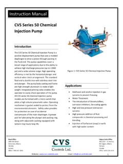
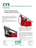
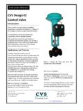
1 CVS Controls Ltd. Process Management and Instrumentation 1 CVS Series 51 Chemical Injection Pump Applications 1. The introduction of De-Emulsifiers, corrosion Inhibitors De-scaling Agents, Solvents and Oxygen Scavengers. 2. Water Treatment 3. Methanol Injection in Gas Pipelines. 4. Injection of Surfactant (Soap) into Low Pressure Gas Wells with high water content Description The CVS gas driven Series 51 Chemical Injection Pump uses a molded diaphragm to drive a piston through chevron packing making it a positive displacement pump, capable of discharge pressures up to 6000 psig,, and maximum volume output up to 30 gallons per day. Unit weight is Lbs, shipping weight is Lbs Traegyr Switch: The Traegyr Switch is a miniature valve offering reliability with rugged construction. The unit consists of a 3-way, 2 position valve which is positively switched with pilot signal valves.
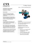
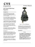
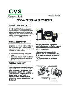
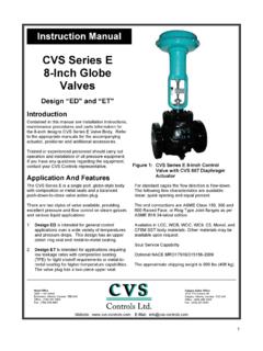
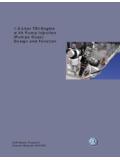
2 The valve offers positive response, extremely low cycle times lower than one stroke per minute, and the pump half stroke feature is easily used. This valve will not stick in mid-position causing the pump to stall and cannot be vibrated or jarred out of position. (Figure 1) Micro Valve: The Micro Valve unit is a miniature valve offering reliability and rugged construction. With an over center, snap action-action operator, the unit consists of a 3-way, 2-position valve. The unit offers sure response, no neutral position, and no varying time lag between positions. Unit maintains either position without holding force, and cannot be vibrated or jarred out of position. (Figure 2) Product Manual F i g u r e 1: CVS Series 51 Chemical Injection Pump with Traegyr Switch Fig ure 2: CVS Series 51 Chemical Injection Pump with Micro Valve Fig ure 3: CVS Series 51 Chemical Injection Pump with Pilot Valve CVS Controls Ltd Product Manual: CVS Series 51 Chemical Injection Pump CVS Controls Ltd.
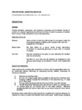
3 Process Management and Instrumentation 2 Description, continued Rotary Switch Pilot Valve: A rotary switch pilot valve (CVS-B-0446) directs the incoming operating gas (35 psi Max) behind the diapragm (CVS-C-0290) which will cause the pump to stroke forward. The valve in turn shuts off the inlet pressure and opens to expel the spent gas behind the diaphragm and the cycle repeats. (Figure 3) A choi ce of three plunger sizes, two stroke lengths and controllable strokes per minute (SPM) with an optional slow speed controller allows for a wide range in capacity, from less than 1 quart to 30 gallons/day. The oil impregnated bronze bushing (not in contact with the gas supply) extends the thrust rod life as well as protects the pump housing. This combined with the enclosed, prelubed flipper arm bearing ensures continued operation in the event that oil is not added to the reservoir. The standard fluid end is ductile iron with stainless steel trim and plunger; all stainless steel is an available option.
4 Installation and Operation The following components should be shipped loose: 1/4 Line Check Valve (One) Stainless Steel: CVS-A-0675 Packing Gland Wrench (One) CVS-A-0315 1. Blow out and remove debris from supply line before hooking up supply air/gas to inlet. Supply pressure should be regulated with a maximum setting of 35 PSI. Note The supply inlet is a 1/4" female connection (Disc Retainer, CVS-A-0906), located at the center of the Pilot Valve (CVS-B-0441). Do not hookup supply air/gas to the small valve; this is the gas exhaust. 2. Install the furnished Line Check (CVS-A-0675) before the Injection point (Note: the direction of the flow arrow). Connect the discharge line to the FNPT in both the line check and the Top Bushing (CVS-A-1496) of the head assembly. Ensure the line is clear of all foreign debris. 3. Ensure the Priming Valve (CVS-A-1497) is partially open.
5 4. *Remove the Wing Screws (CVS-A-0136), Top Cover (CVS-B-0548) and Cover Gasket (CVS-A-1546). Fill the reservoir that houses the Flipper Spring (CVS-A-1821) with approximately one and one-half-pints of non-detergent lightweight oil (SAE 5), fill to bottom of Thrust Rod (CVS-B-0444). 5. Open the main air/gas supply valve and slowly open the small gas Exhaust Valve (CVS-A-2489). The pump should automatically start. Ensure the suction line is primed with fluid and then test the pump head by opening the Priming Valve. The fluid escaping from the Priming Valve may contain bubbles, as soon as bubbles subside close the Priming Valve for normal operation. Adjust pump for the desired Strokes/Min. and pumping rate. Be sure to keep hands away from moving parts. 6. Check the Packing Gland for leakage. If leakage is occurring, use the gland wrench supplied to tighten the gland nut until leak just stops.
6 Do not over tighten the Gland Nut. This may stall the pump or generate excessive wear on the packing and/or plunger. 7. Replace Cover Gasket and Top Cover, secure with Wing Screws. *Note: Step No. 4 pertains to Pilot Valve. CVS Controls Ltd Product Manual: CVS Series 51 Chemical Injection Pump CVS Controls Ltd. Process Management and Instrumentation 3 Maintenance and Troubleshooting A. Keep the cover in place, and periodically oil the thrust rod. B. Regularly check for packing leaks, tighten or replace as required. Note: Ensure the plunger packing is not over tightened, as this may score the plunger and decrease the lifespan of the packing. C. CVS Chemical pumps used for alcohol or methanol Injection must be fitted with Fluoro O-rings. pumps used for most Chemical Injection applications should be fitted with Viton O-rings.
7 The O-rings are located in the Top Seat (CVS-B-0737) and Bottom Seat (CVS-B-0736). Refer to manufacturer specifications for elastomer sealing fluid compatibilities. D. If the pump fails to stroke and air/gas constantly flows from the Air Vent (CVS-A-1836), the diaphragm has ruptured. Disconnect air supply and bleed off pressure. Remove the Diaphragm Cover (CVS-C-0252) and inspect Diaphragm (CVS-C- 0290) for rips and tears, replace as required. Note: If installing a new diaphragm, shutoff and disconnect air supply and ensure the pressure has been bled off. Remove Lock Nut (CVS-A-3320) and Washer (CVS-A-3321) from the Thrust Rod (CVS-B-0444). To prevent the thrust rod from turning, remove the Top Cover (CVS-B-0548) and insert a punch or drift pin into the large hole forward of the Trip Stirrup Assembly (CVS-B-0471). At this point, visually inspect the Return Spring (CVS-A-1821) for damage.
8 E. If no air/gas venting, check the supply pressure (35 PSI Max). Erratic changes in pressure may cause the pump to stall. F. If pump stalls in the forward discharge position, shut off the air/gas supply. First, check if the Flipper Arm Spring (CVS-A-1820) is intact, and then check if the packing gland nut is over tightened. Readjust packing as required. G. If the pump is running, but not pumping, the Injection head could be air locked. Open the priming valve and bleed fluid until no bubbles are present. If still not pumping, the O-ring in the bottom seat may have failed and needs replacing. H. If the Flipper Spring (CVS-A-1820) needs replacement, drain oil into a clean container for later reuse. Shutoff air/gas supply ensuring all pressure is bled off. Remove the Hex Head Machine Screws (CVS-A-0141) and Lock Washers (CVS-A-0425) securing the pilot valve to pump body. Remove the Pilot Valve (CVS-B-0446) and slide the Spring Adapter (CVS-A-1838) off flipper arm and Bearing Assembly (CVS-B-0440).
9 Loosen Hex Head Screw (CVS-A-1829), rotate Stirrup Assembly (CVS-A-1832), and unscrew the flipper spring from Top Spring Adapter (CVS-A- 1838). Replace the flipper spring, slide the pilot valve assembly partially in and reassemble the bottom spring adapter. Secure the pilot valve to pump housing, retighten Hex Head Screw (CVS-A-1829) ensuring it is in the groove on the Thrust Rod (CVS-B-0444). Replace oil and restart pump (See steps 6 &7 under Installation and Operation). I. If micro valve needs replacement, shutoff air/gas supply ensuring all pressure is bled off. Disconnect supply and output tubing. Remove the Hex Head Machine Screws (CVS-A-0141) and Lock Washers (CVS-A-0425) that secure the micro valve plate to pump body. Remove the Micro Valve Switch (CVS-MV-004) with plate (CVS-MV-014) and separate. Mount a new micro valve switch to micro valve plate and secure assembly to body.
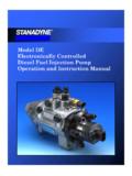
10 Ensure the micro valve extension is centered between both trip arms on trip bar assembly. CVS Controls Ltd Product Manual: CVS Series 51 Chemical Injection Pump CVS Controls Ltd. Process Management and Instrumentation 4 Maintenance and Troubleshooting cont d J. If Traegyr Switch requires replacement, shut off air/gas supply. Make sure all air/gas has been bled off. Disconnect supply and output tubing. Remove the hex head machine screws (CVS-A-0141) and lock washers (CVS-A-0425) that secure the Traegyr valve plate to the pump body. Remove the machines screws that attach the Traegyr plate to the Traegyr Switch. Mount a new Traegyr switch to the plate and secure assembly to body. Ensure the trip arm is located at the home position (located closest to diaphragm side) see diagram below. Orient the trip bar so the rocker arm is rotated toward the diaphragm side ensuring the bearing of the pilot valve is depressed.