Transcription of CVS Self Contained Hydraulic Pump
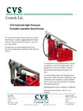
1 Product Manual CVS Controls Ltd. Process Management and Instrumentation CVS self Contained Hydraulic Pump Introduction This CVS Controls product manual includes instructions for the installation, adjustment, maintenance and parts ordering of the CVS self Contained Pump. All CVS Controls equipment should be installed, operated and maintained by qualified personnel. If you have any questions regarding this equipment, contact your CVS Controls representative. Description The CVS self Contained Pump provides reliable emergency shutdown when an external power source or fuel gas is not available or not reliable.
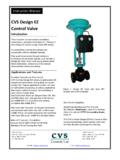
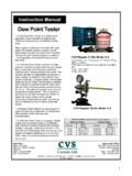
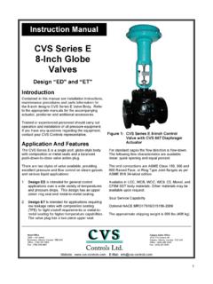
2 The unit uses clean Hydraulic fluid. Used in conjunction with a linear or rotary spring return Hydraulic operator, the CVS self Contained Pump is a fail-safe system which is suitable for ball, plug or other quarter-turn valves as well as reverse-acting gate valves or other linear operated valves. This pump has been proven reliable under the most demanding operating and environmental conditions. It is designed to be the foundation for a flexible sensing and control system, and has built-in temperature compensation and pressure relief. Figure 1: CVS self Contained Hydraulic Pump Installation Generally, the module is installed on the operator by CVS Controls at the manufacturing facility, but can also be field installed by the user.
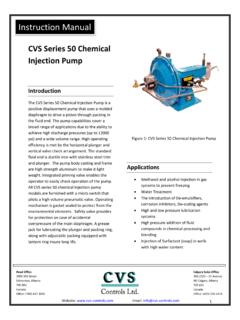
3 The module can be ordered in pressure configurations from 100 psi to 2250 psi. The following connections are marked on the manifold assembly: H: High pressure Hydraulic supply to operator L: Low pressure Hydraulic supply for monitoring devices S: Low pressure Hydraulic signal for RESET VALVE from monitoring or ESD devices V: Vent or return line to allow off-panel devices to return oil to the reservoir CVS Controls Ltd Product Manual: CVS self Contained Hydraulic Pump CVS Controls Ltd. Process Management and Instrumentation 2 SCHP COMPONENT SIGNAL DEVISE AND OPERATOR HIGH PRESSURELOW PRESSURESIGNALVENT (RESERVOIR RETURN)SUCTIONORSHLVHIGH PRESSURELOW PRESSUREVENT Figure 2: Module Schematic This example illustrates the operating method and options for sensing and control.
4 The module is shown with the line valve closed and reset valve unlatched. To operate in this configuration: Latch the reset valve (Key 12), then open the line valve (Key 7) by operating the hand pump (Key 8) When the pilot (Key 5a or 5b) senses that pressure is within the set points the system enters automatic mode The line valve (Key 7) will close if: 1. the reset valve (Key 12) is switched manually, or 2. the pilot (Key 5a or 5b) senses that the pressure is out of rangeCVS Controls Ltd Product Manual: CVS self Contained Hydraulic Pump CVS Controls Ltd.
5 Process Management and Instrumentation 3 Specifications Installation continued Refer to Figure 2 for connections, which are also tagged at the factory. If requested, an optional Solenoid valve may have been installed and tubed at the factory and is ready for electrical connection. A metal or plastic plug may have been installed in the breather/fill port of the reservoir. If that is the case, remove the plug and replace with the breather provided in the bag attached to the unit. Hydraulic fluid used is Esso Univis J13 unless an alternate is specifically requested.
6 Operation Manual Mode (Start Up or Reset) 1. Lift the toggle on the manual pilot valve and latch in the Up position. See Figure 3 for Manual Reset position. 2. Operate hand pump to open/close line until system is pressurized. 3. Stop pumping when high pressure gauge reading is 10% above the minimum value required to hold the valve in position. Note System will automatically reset at set pressure. Note To start up when the system is not completely connected, plug L Low Pressure to prevent fluid flow off the panel. Refer to operation instructions above.
7 Automatic Mode (To Run) 4. Lower the toggle on the manual pilot valve. See Figure 3 for Auto/Run position. The toggle should automatically go to Run . 5. When the signal device(s) is satisfied, the unit will be in automatic mode. The optional Solenoid valve is returned to normal operating condition (either energized or de-energized). Shutdown If the pilot detects pressures outside of the set points, (or if there is an applied or removed electrical signal to the optional Solenoid valve), the pilot removes the signal to the manual pilot valve. The manual pilot valve then switches which allows the spring in the operator to stroke the line valve to the failsafe position.
8 The pilot can also be shutdown manually by pushing the toggle. Components High-pressure SCH Module HP-2-SC or BHP 3 Handpump 0-3000 PSI HP Gauge 0-200 PSI LP Gauge Low-pressure SCH Module HP-2-SC Handpump 0-200 PSI LP Gauge Pressure Settings High-pressure SCH Module HP Relief set at 2250 psi LP Relief set at 135 psi CVS SCR Regulator set at 80-100 psi1 Low-pressure SCH Module LP Relief set at 125 psi Valves Pilot to close valve Reset valve Toggle valve Manual pilot valve (requires 40-60 psi on signal port to sustain auto mode) Optional Solenoid Valve Voltage as specified by user 12-24 VDC 120 VAC with MAWP 150 psi Valve Operator Refer to appropriate manual for specifications Reservoir Low temperature, high impact resin standard (Lexan) Cast aluminum optional.
9 Other Components High/low pressure pilot upper block is connected to the self Contained Hydraulic module with an operating pressure of 60 to 90 psi. Process sensing pressure MAWP depends on the manufacturer. 1. Set to 90 psi at point of manufacturing CVS Controls Ltd Product Manual: CVS self Contained Hydraulic Pump CVS Controls Ltd. Process Management and Instrumentation 4 Maintenance Note: Regular maintenance should be performed each fall, or as required. CVS Controls recommends the use of protective clothing, gloves and eyewear when performing any installation or maintenance.
10 1. Empty fluid reservoir of any accumulated moisture. 2. Check filter element(s) and clean and/or replace as necessary. 3. Check set points on pressure relief valve(s) and reset values if required. 4. If possible, check operation and calibration of pressure pilot or optional Solenoid. 5. Top up Hydraulic fluid. Be sure to use compatible fluid. Troubleshooting Note As shown in Figure 2, the high-pressure side of the system supplies the low-pressure regulated side, therefore any leakage on the low side will cause significant changes in high-pressure gauge values.