Transcription of CVS Series E 8-Inch Globe Valves
1 Website: E-Mail: CVS Series E 8- inch Globe Valves Design ED and ET Introduction Contained in this manual are installation instructions, maintenance procedures and parts information for the 8-Inch designs CVS Series E Valve Body. Refer to the appropriate manuals for the accompanying actuator, positioner and additional accessories. Trained or experienced personnel should carry out operation and installation of all pressure equipment. If you have any questions regarding the equipment, contact your CVS Controls representative. Application And Features The CVS Series E is a single port, Globe -style body with composition or metal seats and a balanced push-down-to-close valve action plug.
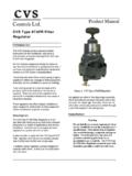
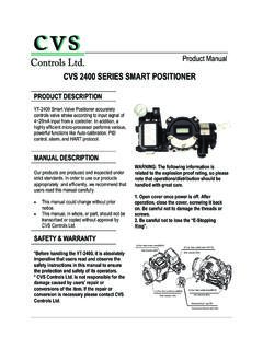
2 There are two styles of valve available, providing excellent pressure and flow control on steam gasses and various liquid applications: ED is intended for general controlapplications over a wide variety of temperaturesand pressure drops. This design has an upperpiston ring seal and metal-to-metal ET is intended for applications requiringlow leakage rates with composition seating(TFE) for tight shutoff requirements or metal-to-metal seating for higher temperature valve plug has a two-piece upper Manual Figure 1: CVS Series E 8-Inch Control Valve with CVS 667 Diaphragm ActuatorFor standard cages the flow direction is flow-down.
3 The following flow characteristics are available: linear, quick opening and equal percent. The end connections are ASME Class 150, 300 and 600 Raised Face, or Ring Type Joint flanges as per ASME edition. Available in LCC, WCB, WCC, WC9, C5, Monel, and CF8M SST body materials. Other materials may be available upon request. Sour Service Capability Optional NACE MRO175/ISO15156-2009 The approximate shipping weight is 900 lbs (408 kg). Head Office 3900 101 Street Edmonton, Alberta, Canada T6E 0A5 Office: (780) 437-3055 Fax: (780) 436-5461 Calgary Sales Office 3516 114 Avenue SECalgary, Alberta, Canada T2Z 3V6 Office: (403) 250-1416 Fax: (403) 291-9487 1 Installation The CVS 8 Series E valve should not be installed in systems that exceed the ANSI specified temperature and pressure ratings.
4 Inspect the Valves for shipping damage and foreign debris when uncrating. the pipe is free of welding slag, chips,and other debris by cleaning out the lines approved gaskets between the valve bodyand the pipeline Controls recommends a standard three-valve maintenance bypass be installed. Thisallows isolation of the valve body withoutshutting down the pipeline the valve so that the flow direction arrowon the body coincides with the actual processflow through the the valve can be installed in anyposition, the typical installation has the actuatorvertical above the valve body. Support for theactuator will be necessary if there is vibration inthe line or if the valve body is positioned 45degrees or more below Before beginning any maintenance, it is important to isolate the control valve and release all pressure contained in the valve body and the actuator.
5 Disconnect any operating lines providing air pressure, control signals or electrical power to the actuator. Note: Caution must be used in the disassembly. The seating surfaces and surface finish of the cage; seat ring, stem, and plug are critical for proper sealing. Nicks and scratches will affect the ability to seal the valve in the future. Disassembly and remove the actuator from the nuts or cap screws from the one of the actuator stem locknuts ontothe stem and continue threading it down to thebottom of the thread run the bonnet by lifting it straight up with ahoist. Attach the hoist by either a double cablehoisting sling under the bonnet or by the liftingrings attached to the packing flange stud bolts oron the 5 yoke bosses to two yoke stud bolts180 must be used when lifting the bonnet toensure that it clears the body and stud boltscompletely.
6 Any damage to the seating surfacewill compromise future sealing prevent damage to the seating surface, placethe bonnet-valve plug assembly on a wooden orcushioned the Plug Stem or Load Ring the locknuts from the the packing flange the bonnet the plug and stem out of the valve plug is damaged it will be necessary toreplace both the valve plug and stem. If thestem is damaged, a new valve stem can beinserted in the original valve the Stem the old groove the old stem, and replace with newstem. the new stem until the thread bottomsout against the through the stem using the hole in the valveplug as guide. Remove any chips or burrs anddrive in a new groove pin to lock the to Table 1 for groove pin drill 2: Groove Pin Pilot Holes 2 Table 1: Stem Torque and Groove Pin Drill Sizes Valve Stem Connection (VSC) Torque Min/Max Values Groove Pin Drill Size Inches mm Lbf-Ft N m Inches 3/4 237-339175-2503/16 1 420-481310-3551/4 Note: Use a new groove pin when installing a new stem.
7 Vibration may loosen the stem if using an old groove pin. Assembly all gasket surfaces are the valve plug piston ring or seal ringwith a new for CVS ED Design Bodies:For valve bodies using a carbon filled TFE piston ring, at the split, slightly spread the ring and install it over the stem and into the piston ring groove on the valve plug. Graphite piston rings are supplied as a complete ring and must be broken into two sections. The piston ring can be broken in half by scoring, and then breaking over a hard surface ) edge of a table. Ensure the broken ends are re-matched when the piston ring is installed in the piston ring groove.
8 CVS ET Design Bodies: Apply a lubricant to both back-up ring and seal rings. Install the back-up ring over the stem and into the piston ring groove. Place the seal ring over the top edge of the valve plug, so that it slips into the groove on one side of the valve plug. Cautiously stretch the seal ring to work it over the top edge of the valve plug. Avoid jerking sharply on the seal, as the TFE in the seal ring needs time to cold flow during the stretching procedure. This stretching procedure may make the seal ring seem loose in the groove, however it will contract to its original size after installation of the cage. the seat ring gasket, and install the seatring.
9 If using a composition seat (TFE),assemble it by placing the TFE disc onto the discretainer and then sliding this assembly over thedisc the cage onto the seat ring. Any rotationalorientation of the cage with respect to the valvebody is ensure a good seal, clean all sealing surfacesand examine surfaces for nicks and the bonnet gasket in the valve plug assembly in the cage, andthen position the load ring on top of the the bonnet on the body ensuring that thepipe plug (or lubricator) is on the downstreamside of the good bolting practices, bolt the bonnet tothe body. Lubricate the studs and nuts usinggood quality lubrication.
10 Tighten the boltsalternately. Correct tightening of the bonnetbolts accomplishes two To compress the bonnet gasket to form a seal with the body joint. Bolt loads are transmitted to the cage through the load ring, which creates a sealing load for the seat ring gasket. the actuator to the bonnet and make upthe stem connection. Refer to Making Up theStem Connection for proper Lubrication The use of semi-metallic packing requires the use of a lubricator or lubricator/isolating valve (Figure 3). The lubricator or lubricator/isolating valve is mounted in place of pipe plug (Figure 3, Key 15). For standard service up to 450 F, use Dow Corning lubricant or equivalent.