Transcription of CVS 2400 SERIES SMART POSITIONER
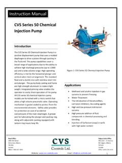
1 Product Manual CVS 2400 SERIES SMART POSITIONER PRODUCT DESCRIPTION YT-2400 SMART Valve POSITIONER accurately controls valve stroke according to input signal of 4~20mA input from a controller. In addition, a highly efficient micro-processor performs various, powerful functions like Auto-calibration, PID control, alarm, and HART protocol. MANUAL DESCRIPTION Our products are produced and inspected under strict standards. In order to use our products appropriately and efficiently, we recommend that users read this manual carefully. This manual could change without prior notice. This manual, in whole, or part, should not be transcribed or copied without approval by CVS Controls Ltd. SAFETY & WARRANTY *Before handling the YT-2400, it is absolutely imperative that users read and observe the safety instructions in this manual to ensure the protection and safety of its operators.
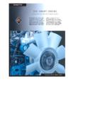
2 * CVS Controls Ltd. is not responsible for the damage caused by users repair or conversions of the item. If the repair or conversion is necessary please contact CVS Controls Ltd. WARNING: The following information is related to the explosion proof rating, so please note that operations/distribution should be handled with great care. 1. Open cover once power is off. After operation, close the cover, screwing it back on. Be careful not to damage the threads or screws. 2. Be careful not to lose the E-Stopping Ring . (2) Hex. Head socket screw(M6x20) Don t unscrew (4EA) (3) Hex. Head socket screw (M4X 15) Don t unscrew (2EA) (1) Hex. Head socket screw(M4x5) Don t unscrew (1EA) Retaining Ring E type (#7) Don t remove from the shaft (1EA) (4) Hex.
3 Head socket screw(M5x25) Don t unscrew (5EA) Confirm the operating conditions so that the explosion proof rating is available and ensure not to use beyond that rating. The explosion proof of the YT-2400 is flame-proof, which is marked ExdIIBT6. and can be used in Zone 1 & 2. In hazardous areas with explosive gas, ensure connecting explosion proof conduit or pressure-proof packing cable must be sealed using a gasket. Notes on Maintenance of Explosion Proof Structure in Hazardous Area 2 CVS Controls Ltd. Product Manual: YT-2400 SMART POSITIONER CVS Controls Ltd. Process Management And Instrumentation Confirm that the power is shut off before opening the cover. When opening the PCB Terminal or cover, of the terminal or PCB, the current or voltage must not remain in the wires or electronic parts after the power is shut down.
4 YT-2400 has two conduit entries. When one explosion proof conduit or pressure-proof packing cable is used, the other port must be blocked to ensure explosion proof rating. 3 CVS Controls Ltd. Process Management And Instrumentation CVS Controls Ltd. Product Manual: YT-2400 SMART POSITIONER FEATURES and FUNCTIONS 1. There are four buttons on the outside of the posi-tioner which allows for adjustment of parameters and menus without opening the cover in explosive gas areas. 2. The SMART POSITIONER is ExdIIBT6 explosion proof rated. 3. Endures severe vibration. 4. The pilot relay valve is installed on the outside of the POSITIONER body, which allows for easy serviceability. 5. It operates normally regardless of the change in supply pressure during operation.
5 6. This POSITIONER is easy to auto-calibrate. 7. Its compact size allows for easy installation on small actuators. 8. Plant operating costs may be reduced due to its low air consumption. 9. Due to the low voltage ( ) usage, there is no limitations with the controller. 10. An adjustable orifice is used to accommodate small actuators so control is optimized during operation. valve POSITIONER has HART communication capability. 12. The POSITIONER output uses an analog feedback system. 13. An alarm function is available when using a limit switch. 14. Available valve flow characteristics are linear, quick opening, and equal percent. 15. Specific flow control is available with 16 specified user points.
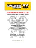
6 16. Tight shut-off and open can be set by the user. 17. Regulated filtered air flows to the actuator by using the A/M switch. 18. Split range input is 4-20mA, 12-20mA. 19. The Hand Calibration function can be used to set zero and span. POSITIONER has a self diagnose function for greater reliability. 21. It is equipped with a manual override. 22. The protection class is IP 66. 23. The epoxy powder coating allows for long periods of exposure to a corrosive environment. 24. Very easy to maintain with its modular design. 4~20 mA INPUT (10-30V) Feed Back Signal Limit Limit V+ V- OUT V- OUT V+ V+ OUT Voltage V- OUT load Circuit Detecting Limit Load Out Voltage Limit Switch Circuit STRUCTURE The structure of the YT-2400L is as follows.
7 The YT-2400R is the same as the linear type except for the feedback lever. 4 CVS Controls Ltd. Process Management And Instrumentation CVS Controls Ltd. Product Manual: YT-2400 SMART POSITIONER Button Cover Body Cover Potentiometer Main Shaft Terminal Cover Pilot Relay Cover Pilot Relay Manifold PCB Main Piezo Terminal Plate Feedback Lever Feedback Spring Flange Nut Base Body Filter Plug Variable Orifice YT-2400L (Linear Type) YT-2400R (Rotary Type) FEATURES & FUNCTIONS 5 CVS Controls Ltd. Process Management And Instrumentation CVS Controls Ltd. Product Manual: YT-2400 SMART POSITIONER INSTALLATION NOTE: When the POSITIONER is installed or replaced with the actuator, ensure the following: WARNING: To avoid damage to the process system or personal injury, isolate the valve from the system and relieve any pressure contained within prior to disassembly.
8 Disconnect any operating lines providing air pressure, control signals, or electrical power to the actuator. TOOLS FOR INSTALLATION Tools and bolts used for assembly are: 1. Hexagonal wrenches 2. (+) screw driver 3. (-) screw driver 4. Spanners for hexagon head bolts YT-2400L Installation YT-2400L is used for linear motion valves such as globe valves or gate valves using spring return type diaphragm actuators or piston actuators. YT-2400L consists of the following components. Be sure that all the components are prepared. 1. YT-2400 body 2. Feedback lever and spring lever 3. Flange nut (attached on the body of the main shaft of the YT-2400L body) 4. 4 pcs of hexagon head bolt 5.
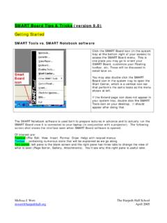
9 4 pcs of M8 plate washer 6 CVS Controls Ltd. Process Management And Instrumentation CVS Controls Ltd. Product Manual: YT-2400 SMART POSITIONER 6 4-M8 TAP 50 5 12 12 60 YT-2400L Drawing 60 4-M3 TAP 12 30 50 5 YT-2400 Installation Example YT-2400R Drawing 7 Installing YT-2400L with Bracket 1. It is necessary to make a proper bracket to attach onto the actuator yoke. The most important notes in making the bracket are as follows: A) YT-2400L feedback lever should be level at 50% of the valve stroke (Refer to point #7) B) Feedback lever connection bar of the actuator clamp should be connected at the position that the valve and stroke numbers engraved on the feedback lever match. (Refer to point #8) If the bracket meets the above conditions, installation of the YT-2400L is simple.
10 2. Assemble the YT-2400L and bracket with supplied bolts. 3. After assembling the YT-2400L attach it using the bolt holes of the actuator yoke. Do not tighten bolts completely - there must be some space remaining. 4. Install the bar connected to the YT-2400 feedback lever on the actuator clamp. The slot length between the YT-2400L feedback lever is , so the diameter of the connection bar should be less than 5. Temporarily connect the air filter regulator to the actuator temporarily. Set the supply pressure of the air filter regulator to ensure that the actuator clamp is positioned at 50% of the valve stroke. 6. Insert connection bar attached on the actuator clamp into the slot of the YT-2400 feedback lever.