Transcription of MODEL EJ500 INSTALLATION AND OPERATING …
1 MODEL EJ500 INSTALLATION AND OPERATING INSTRUCTIONSR atings500W single gang or 2 gang installations (40W minimum)4A Tungsten (Incandescent)4A Ballast (Inductive)120 VAC, 60 HzOperating Temperature: 0 deg C - +40 deg NOTES: This switch is suitable for use in up to 2 gang installations. EJ500 is designed to operate standard incandescent lightbulbs or (thermally protected Class P ballast) fluorescentlighting ONLY. The switch can handle a minimum load totaling 40 Watts. This device is NOT TO BE USED to operate MERCURYVAPOR LIGHTS, APPLIANCES, RADIOS, TV s, STEREO s, etc.
2 Separate dimmers and photoelectric switches cannot beused in combination with your timer. It is recommended that your timer not be used with PAR or R type outdoor flood lamps or lamps larger than 150 watts,since currents generated during lamp burn-out could dam-age the you for purchasing Intermatic EJ500 Indoor Wall Switch Timerwith Astronomic Feature. This timer can replace your regular or 3-way light switch (where two switches control the same light) tocontrol incandescent and fluorescent lights.
3 (See important notes)You will need a Decora style wall plate with this timer (wall plate notincluded).Features Automatic or manual operation. Push the controlcover to switch ON or OFF at any time. Program up to 7 ON/OFF setting pairs. Automatic Daylight Savings Time (dST) option. Multiple daily settings options:o All days of the weeko Individual days of the weeko 5 weekdayso 2 weekend days LCD digital clock and readout. Random feature automatically varies switching times for a lived-in look. Two SR44/LR44 batteries keep time for up to 3 months, ofpower interruption.
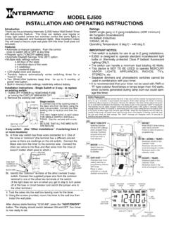
4 Built-in memory holds settings indefinitely without instructions - Single Switch or 3-way - to replacean existing switch:1. TURN OFF POWER by REMOVING FUSE or turning the CIRCUIT BREAKER Remove the existing wall switch. 7/16 Trim building wires bare to 7/16 .BLACK WIREBLUE WIRERED WIRE (Capped,Not Connected)Single switch:3. Connect one of the building wires tothe black wire from the timer, using thewire nuts provided. Connect the otherbuilding wire to the blue wire from thetimer. THE RED TIMER WIRE IS NOT USEDFOR SINGLE SWITCH INSTALLA-TIONS.
5 Cap the red wire with a wirenut. BE SURE THAT ALL THE WIRE NUTSARE switch: (See Other Installations if switching from 3or more locations)3a. Athree way switch has three wires connected to it. One of the wires is common (the terminal has a different colored screw or there are markings on the old switch). Connect the Black wire from the timer to the common wire. Connect the other two wires to the Blue and Red wires from the timer (it doesn t matter which goes to which.)WIRE FROM COMMON OF OLD SWITCH BLACK WIRERED WIREBLUE WIREREMOTE3-WAYSWITCHMOVEJUMPER WIRETO OTHER TERMINAL IF THISSWITCHDOES NOTTURN LIGHTONCOMMON3b.
6 Identify the common terminal at the other (remote 3-way) switch. Connect the supplied jumper wire from the common terminal to one of the other two terminals of the switch. (If the light does not turn on when you get to step 6, turn power off at the fuse or circuit breaker and switch the jumper wire to the other terminal.)4. Tuck the wires into the wall box leaving room for the Using the screws provided, mount the timer to the wall box theninstall the wall display starts flashing "12:00 AM", press the "NEXT/ON/OFF"button.
7 The display should switch between ON and OFF. Your timer is now ready to set. Battery ReplacementThe two LR44/SR44 batteries maintain the time of day clock and the calendar during power interrup-tions, for up to 3 months of accumulated interruptions. All the other settings will remain in memoryindefinitely without batteries or AC power. Remove the batteries if the timer will be without AC powerfor an extended the batteries if the display is dim or the message lobAT is batteries may be safely changed without removing AC power.
8 If AC power is removed, pleasechange batteries within 15 seconds to avoid losing your time of day the battery hold-er by prying at either finger hole, left and right of holder. Install the new batteries into the holder asmarked inside holder. Re-install holder with the notch down. If the display is flashing 12:00 AM, resetthe time and check the date settings. The lobAT message will disappear within 10 seconds ofinstalling new good from oneprogram mode to and OFFsettingswhen programmingthe timer.
9 Confirmsprogram entry andadvances timer tonext while holdingdown NEXT/ON/OFFbutton to clear all + ZONE+ YEAR+Advances months in thecalendar minutes in theclock and program in thecalendar + YEAR-Subtractsyears in thecalendar hours in theclock and program days whensetting calendar orprogramming ON andOFF to selectautomatic or manualdaylight savings #AUTODAYLIGHT SAVINGSONSETTINGAM or PMINDICATORDAYS OF THE WEEKFig. 1 Glossary of TermsAstronomic Feature The EJ500 Wall Switch Timer with Astronomic Feature automatically compensates for changes in the length of daylight throughout the example, the sunset in Chicago, IL varies from approximately 4:30 PM during December to approximately 9:00 PM during June.
10 The EJ500 automaticallyadjusts for changes in daylight. SET THE TIMER ONCE AND NO RESETTING, BECAUSE OF DAILY TIME CHANGES, IS Savings Time (DST) The EJ500 timer has an automatic Daylight Savings Time feature. The AUTO setting will adjust for daylight savings time MAN setting prevents automatic DST adjustments. Program Zone (See Fig 7) The Astronomic program divides the United States into 3 zones. The NORTH Zone refers to locations from Chicago, IL CENTRAL zone refers to locations between Chicago, IL and southern Missouri.