Transcription of Model PR-274/275 - MAMAC Sys
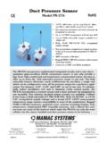
1 Model PR-274/275 Low Pressure TransducerTechnical InformationRev. 07400 Flying Cloud Drive Minneapolis, MN 55344-3720 USA800-843-5116 952-835-1626 Fax additional information, see the accompanying data sheet for this InformationDimensionsFigure 1. Pressure Transducer DimensionsSpecificationsAccuracy*: 1% FSOverpressure: 10 PSIDS upply Voltage: 12 - 40 VDC;12 - 35 VAC (VDC output transducers only)Supply Current: 10 mA maximum for VDC output transducers; 20 mA maximum for mA output transducersEnclosure: 18 gage steel NEMA 4 (IP65) or panel mount chassisFinish: Baked-on enamel PMS2GR88 BCompensated Temperature Range: 25 F to 150 F (-4 C to 65 C)T.
2 C . E r r o r: F (.02%/ C)Operating Temperature Range: 0 F to 175 F (-18 C to 80 C)Media Compatibility: Clean dry air or any inert gasEnvironmental: 10 to 90% RH non-condensingTermination: Unpluggable screw terminal blockWire Size: 12 gauge maximumLoad Impedance: ohms maximum at 40 VDC (mA output transducers)1K ohms minimum (VDC output transducers)Weight: Enclosure mount: lb. (.45 kg); Panel mount: (.25 kg)* Includes nonlinearity and InspectionInspect the transducer packaging for signs of damage. If damaged, notify the carrier Tools (not provided):-Digital volt-ohm meter (DVM)-Appropriate screwdriver for mounting screws-Appropriate drill and drill bit for mounting screws Appropriate accessories Two #8 self-tapping mounting screws (not provided) Training: Installer must be a qualified and experienced technicianWARNING!
3 Disconnect the power supply before installing the transducer. Failure to do so can result in electrical shock and equipment damage. Make all connections in accordance with the job wiring diagram and national and local electrical codes. Use only copper conductors. Use electrostatic discharge precautions such as wrist straps when installing and wiring the transducer. Avoid installing the transducer in locations where severe shock, vibration, excessive moisture, or corrosive fumes are present. NEMA 4 housings are primarily intended for outdoor use to provide a degree of protection against windblown dust, rain, and hose-directed water.
4 Do not exceed ratings for the the transducer cover using a Phillips the mounting the transducer on a vertical surface with two number eight self-tapping screws (not provided). the wires through the bottom of the enclosure and make the necessary the cover and make the pneumatic 12 AWG wire maximum for wiring terminals. Use flexible 1/4-inch outer diameter (5/32-inch inner diameter) tubing for the high and low pressure connections. See Figures 6 to 9 for wiring diagrams and Figures 10 and 11 for jumper for mA the blue terminal block by carefully pulling it off the circuit board.
5 See Figure the [+] and [-] terminal markings on the the supply voltage to the [+] the 4 - 20 mA output ([-] terminal) to the controller s input that the power supply common is attached to the common bus of the the terminal block to the circuit board and apply power to the for the appropriate output signal by using a DVM set to DC milliamps connected in series to the [-] 4. Pressure Transducer With mA OutputWiring for VDC OutputThe VDC output low pressure transducer is field selectable for 0 - 5 VDC or 0 - 10 VDC output and can be powered with either 12 - 40 VDC or 12 - 35 VAC.
6 The blue terminal block by carefully pulling it off the circuit board. See Figure the [+], [-], and [0] terminal markings on the the power wires to the [+] and [-] terminals. The [-] terminal is also the negative output the [0] terminal, which is the positive VDC output terminal, to the controller s the terminal block to the circuit board and apply power to the the appropriate VDC output by using a DVM set to DC volts connected to the [0] and [-] ! If using grounded AC, ensure that the hot wire is on the [+] terminal. In addition, if using a controller without built-in isolation, use an isolation transformer to supply the transducer.
7 This transducer contains a half-wave rectifier power supply and must not be powered from transformers powering other devices with non-isolated full-wave rectifier power supplies. When multiple transducers are powered from the same transformer, damage will result unless all 24-gage power leads are connected to the same power lead on all transducers. Maintain the correct phasing when powering more than one transducer from a single 5. Pressure Transducer With VDC OutputPACKAGINGRANGEOUTPUT274 (enclosure mount)275 (panel mount)R1 ( wc)R2 ( wc)R3 ( wc)R4 ( wc)R5 (pa)R6 (pa)R7 (pa)R8 (pa)
8 0 to / to to / 0 to / 0 to to / to to to / 0 to / 0 to to / to / to to 30 / 0 to 15 / 0 to to / to to to 25 / to to 250 / 0 to 125 / 0 to /-125 to 125 / to to to 1250 / 0 to 625 /0 to / -625 to 625 to / to to 7500 / 0 to 3750 /0 to 1875 / -3750 to 3750 / -1875 to 1875 / to - 20 mA two-wire0 - 5 or 0 - 10 VDC(field selectable)Figure 2. Enclosure MountTransducerFigure 3. Panel MountTransducerPage 2 of Applications (wiring diagrams)Figures 6 and 7 illustrate typical wiring diagrams for the mA output low pressure 6.
9 Wiring mA Output Transducers With an ExternalDC Power SupplyFigure 7. Wiring mA Output Transducers Where the Controller or Meter Has an Internal DC Power SupplyFigures 8 and 9 illustrate typical wiring diagrams for the VDC output low pressure 8. Wiring VDC Output Transducers With an External ACPower SupplyFigure 9. Wiring VDC Output Transducers With anExternal DC Power SupplyAdjustmentsJumper ConfigurationJumper configuration varies according to the output type of the low pressure transducer. Range configurations are shown in Table 1. Jumper selections for mA output low pressure transducers are shown in Figure 10; jumper selections for VDC output low pressure transducers are shown in Figure 10.
10 Jumper Selections for Pressure Transducers With mA OutputFigure 11. Jumper Selections for Pressure Transducers WithVDC that the transducer is mounted in the correct the appropriate input signal and supply the appropriate configuration ! Never connect 120 VAC to the pressure transducer. AC voltage should never be connected to a transducer intended for a DC power the pressure to obtain the maximum output signal for the appropriate that output is either 20 mA or 5 or 10 the pressure to obtain a minimum output that output is either 4 mA or 0 :This pressure transducer is a highly accurate device.