Transcription of MODEL REVIEW Pz.Kpfw. III, Ausf.M (with Schurzen) Dragon ...
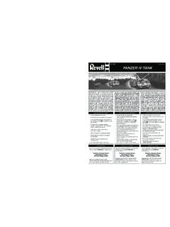
1 MODEL REVIEW III, (with Schurzen) Dragon Models, 1:72 Reviewed by Joe LoMusio The panzer III was an improvement of the previous J through L versions, with extra superstructure front and mantlet of 20 mm of armor. It also was equipped with fording exhaust which allowed deeper river crossings. The gun was the standard long barrel 50 mm ( in) KwK 39 L60. It also had six 90 mm NbK smoke dischargers, three mounted on each side of the turret. The could also be equipped with protective steel plates, called Schurzen, designed to protect the turret area from enemy anti-tank weapons. Further armor protection were large steel plate skirts suspended from either side of the chassis. A total of 1000 were ordered, but only 250 were completed.
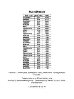
2 The panzer III took part in the greatest tank battle of all time, the Battle of Kursk in July 1943. It is the Kursk Panzers that are depicted in this Dragon s 1/72 Armor Pro series. The kit: The Dragon kit is well engineered, with finely molded parts needing very little cleanup. Included in the highly colorful box (depicting a battle scene from Kursk) are five sprues totally some 109 parts, 44 of which are the road wheels and main sprocket wheels on sprue D. The Chassis, turret and top deck are separate parts. There are two Photo etched frets, one with the Schurzen plates and the other with additional detail for the top front of the turret. The tracks are finely molded one piece rubber band tracks. The small decal sheet is well represented by Cartograf decals, and provides for the markings of three tanks , Div, LAH , and , all from Kursk in 1943.
3 The build: The Instructions are divided into ten steps and the build is pretty straight forward. However, I did make some decisions that departed from the order of the instructions that I will mention during the steps involved. One minor criticism I might offer is that the arrows in the drawings are not always clear enough to where the part goes. This is usually remedied by just taking some time and being careful to dry fit and then determine the most obvious placement location. Another criticism would be that the box art, as well as the paint and decal suggestions for the above mentioned tanks, depict spare tracks stowed at the front of the tank in a spare track rack, but there are no spare tracks provided in the kit! I guess Dragon assumes you have a good supply of the exact size and patterned tracks in your spare parts box to add these. That simply may not be the case.
4 If you are building this kit OOB, then you will have to leave off any tracks you might find elsewhere (as I had to do). I treated the PE parts to a bath in White Vinegar to prime them for painting later on. All the wheels (return rollers, idler wheels and road wheels) have only one attachment point on their respective sprues, and that is very helpful as it cuts your cleanup in half (given that most wheels have two attachment points on most sprues). However, the two sprocket wheels had double injection attachments on either side of the wheel (a total of four points) which were located right on the tips of the sprocket. Some care needs to be given here to clean up those nubs and retain the sharpness of the point of the sprocket. Another slight problem, this time with the instructions, has been reoccurring. From previous reviews I could see that a misidentification of a part has still not been corrected by Dragon .
5 Jim Pearsall, in his REVIEW of the same tank, but the version with the wading Muffler, pointed out that in Step 3, part A5 is misidentified as A10, and that part A10 is not identified at all. Then I noticed that the instructions point out that part B11 is supposed to be glued to the right side of A10, but B11 is shaped to be fixed to the left side, not the right side, which receives B12. You will see this clear enough for yourself, as the parts affix to a recessed area on A10 and can only go in one way. The Turret is a beautiful piece with just enough detail. The gun barrel has the front end drilled out slightly, so that is helpful, and there is only a very slight seam to lightly sand off. The very small tow ring, part A24, is solid and needs to have a hole drilled through both halves of the piece. In Step 4, part A28 is shown being attached to the back of the turret, and then the stowage bin, part A27, being installed directly over that.
6 I found it easier to fit A28 into the cavity of A27 first, fix it with some Tamiya Extra thin glue, and then later, simply install the completed stowage bin directly onto the back of the turret. A real oddity in the instructions and parts numbering occurs in Step 8, where the antenna is identified as part A37. However, A37 is shaded out in the sprue composite drawing (meaning that it is not supposed to be installed), not to mention that it, along with A38, are not antennas at all, but the storage trough for the antenna. This can be really confusing, as Jim Pearsall acknowledged in his REVIEW as well. There will be another problem with this part later, but for now just realize that no antenna is provided and you will have to make one yourself. This is easily done, of course, as some stretched sprue does just fine (and using sprue from the kit allows you to maintain your out-of-box requirements, if that is your intention).
7 While I am mentioning the common feature of shading out parts on the composite sprue drawing to alert you to parts that are not supposed to be used, it may be helpful to point out that a number of parts were never referred to in the step by step build instructions and yet they were not shaded out in the composite. This would include parts B13 and B14, B15 and B16, as well as parts A19 and A21. Care should be given to the removal of the brackets for the Schurzen (Parts B5 through B10 on the supplement B sprue). These are very small, thin and delicate plastic parts and can be easily snapped in two, either in detaching them from the sprue or in cleaning them up. Further care must be given in their exact placement on the turret as well. They can only be installed a certain way if you are going to achieve the desired angles for installing the plates that make up the Schurzen.
8 A helpful suggestion would be to wait to install the two extension fender panels one either side of the tank chassis until after you have installed the tracks. The installation steps have you installing the fender panels first (Step 6) and then the tracks later (Step 9). It was so much easier to install the tracks without having to negotiate around and under the fender panels. Once the tracks are in place and secured, the side fender panels can then be added on above of them. Now, getting back to the antenna problem, I installed the antenna trough (A38) on the right side fender panel as there were holes to receive it. Then later, as I was finishing installing the side armor shields (Step 10) with the brackets, I discovered that both the middle bracket and the back bracket on the right side could not possibly connect to their corresponding attachment points because of the antenna trough.
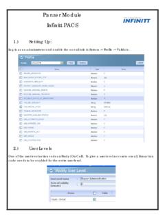
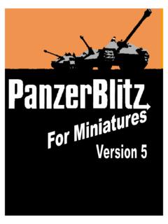
9 I had to pry that piece loose, so that I could install the important and necessary brackets. Now I had an exposed hole where the trough had been installed, and instead of filling it and having to re-do the painting and weathering, I decided to cut the trough and only install a partial length of it, as it would still be useful in holding the antenna once stowed. Painting and Weathering: I decided I wanted to depart from the camo schemes suggested for all three tanks in the Painting & Markings section of the instructions. Instead, I wanted to depict my panzer III in a winter camouflage scheme. I would still employ the markings for 1 LAH , thereby taking advantage of the decal sheet provided with the kit. I first primed the MODEL with Tamiya Grey Primer, followed by Vallejo Dark Yellow (71025) as my base coat. Once dry, I followed that with a light coat of Vallejo Air White, mixed with just a drop of Light Grey.
10 After allowing that coat to sit for about 30 minutes, I begin rubbing Tamiya Thinner over selected areas with a stiff brush. This accomplished loosening and streaking the white winter overcoat, as this was actually field applied by German tank crews (usually a mixture of white chalk and water). Further chipping was accomplished with Vallejo Burnt Umber. All the road wheels were painted with Vallejo Black (70950) with the inner hub surfaces painted with the same Dark Yellow as the tank body. The Exhaust was coated with a mixture of Vallejo Rust and Vallejo Steel, and after drying, coated with some rust color pigments and powders. The Tracks were first painted with MODEL Masters Stainless Steel Metalizer and then treated to a black acrylic wash by the relatively new line of Testors CreateFX Acrylic Washes. That wash was then followed by a thin coat of Vallejo Oxide Rust wash (76506).