Transcription of Model SM95 - International Sensor Technology
1 Model SM95 Sensor TransmittersFOR OXYGEN, CATALYTIC, ELECTROCHEMICALAND SOLID STATE SENSORSI nstallation and Instructions Manual3 Whatney Street, Irvine, California 92618 Phone: 949-452-9000 Fax:949-452-9009E-mail: Website: MANUAL FOR SM95-S, SM95-C,SM95-E, & SM95-O Sensor TRANSMITTERSIMPORTANT READ FIRST!This manual contains operating instructions for stationary gas monitoring instruments designed for area air quality andsafety applications, and should be STUDIED CAREFULLY by all persons responsible for the operation and mainte-nance of the instruments. All International Sensor Technology ( ) equipment described herein is designed or manu-factured for use only as set forth herein and by the labels affixed, or other literature accompanying the WARNINGS or CAUTIONS are herein set forth, they must be followed.
2 If equipment is used in a manneror under conditions not specifically authorized or prescribed by this manual, or by other materials or written instructionseither accompanying the product or authorized by in writing, or if it is used or maintained by unqualified orimproperly trained personnel, International Sensor Technology disclaims all responsibility of every kind for said basic connection installation instructions are included, all equipment must be installed by qualified electriciansFOLLOWING ALL ASPECTS OF THE LOCAL CODE REQUIREMENTS. Also, the instruments must be calibrated andalarms tested periodically by trained personnel for proper functioning of the : The overall system, especially where gas monitoring sensors are used, must be CALIBRATED BY QUALI-FIED PERSONNEL.
3 Initial calibration should be performed after installation, then weekly for at least the first month ofoperation. Thereafter, a monthly calibration check is recommended to assure reliability and call the factory if any problems are sensors and instruments are designed for area air quality and safety applications. IST gas monitoring instrumentsare provided with a one year warranty (commencing on the shipment date from the factory). This warranty coversonly defective parts or workmanship in normal use and service. Instruments which fail to function due to factory defectwithin one year of date of shipment are to be returned to International Sensor Technology for warranty will determine the nature and responsibility for the defect.
4 In all cases the warranty is limited to the original cost ofthe equipment. Any misuse of equipment is the customers responsibility. IST will either repair or replace (at IST soption) returned instruments subject to the warranty, at no charge. No field service is included in this warranty. Forfield service requirements please contact addition to the one year warranty on instruments, IST warrants the Sensor ELEMENT itself against failure due todeterioration or defect, as follows:1. Solid State Sensors 3 years2. Catalytic Sensors 1 year3. Electrochemical Sensors (including O2) 1 year4. Infrared (IR) 1 yearThis warranty is voided by:1.
5 Improper application of Misuse of Intentional or accidental damaging of Not returning the Sensor to factory for warranty any queries regarding warranty repair or replacements, please include the instrument Model and serial number inany transmittals to IST. All equipment returned to IST (including warranty repairs) must be accompanied by an instruments are supplied with operating and installation manuals and other literature. These are the only sourceof specific details regarding proper operation and maintenance of the equipment. These instructions must be care-fully read and the precautions followed in detail. Instruments must be calibrated and alarms checked periodically toassure proper equipment operation.
6 Please refer to the manual for of Contents1. 22. 23. Wire .24. 2A). Adjusting the Zero 3B). Adjusting the Span 35. Calibration Gas 3 Zero 3 Span 36. Calibration of Oxygen 3A). Adjusting the Zero Point Enrichment 4B). Adjusting the Span Point Enrichment 4C). Adjusting the Ambient Point Deprivation 4D). Adjusting the Deprivation Point Deprivation 47. SM95-E Rev. E and Type II Electrochemical 48. Sensor Heater Voltage (SM95-S & SM95-C).. 59. Output 510. Replacing a 511. Installation/Location of Sensor 512. Frequently Asked 613. Spare 72SM95 Sensor TRANSMITTERS1. INTRODUCTIONThis manual describes the installation and operating instructions for International Sensor Technology s (IST) Model SM95sensor transmitter.
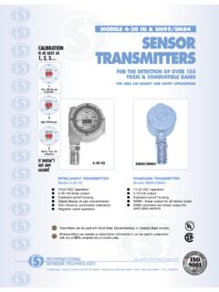
7 These instructions cover the family of transmitters: Solid-State (SM95-S), Catalytic Bead (SM95-C),Electrochemical (SM95-E) and Oxygen (SM95-O). These transmitters can operate as stand-alone units or can be used inconjunction with a variety of controllers available from IST. They are housed in an explosion proof casing, operate on 14-24 VDC and produce a 4-20 mA linear output proportional to the gas concentration. The wide power supply variation allowsplacing the transmitters away from the power supply due to attenuation of the signal (voltage drop) over distance. Minimumvoltage AT THE TRANSMITTER is 14 VDC. The transmitter has been calibrated at the factory and is ready to be WIRINGT hree-conductor cable is required for each Sensor transmitter.
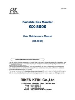
8 These connections are made to terminalson the circuit board inside the Sensor transmitter. The socket for this connection is included in the transmit-ter. The terminal s designations are as follows:1) POWER: +14 to +24 VDC input2) SIGNAL: Linear 4-20 mA output3) GROUND Figure 1 - The terminal block socket is provided within the transmitter3. WIRE DISTANCESThe maximum distance that wires can be run for the SM95 Sensor transmitter is dependent on both the wire size used as wellas the power supply voltage. The SM95 can operate on any voltage between 14 and 24 VDC. When used in conjunction withIST s MP SERIES of controllers, these controllers provide 24 VDC to the Sensor transmitters.
9 Following are maximum wiredistances vs. wire gauge for a 24 VDC power One- Way Distance (Feet) One- Way Distance (Meters)#182300710#1637001100#1459001800 #1294002800 Using an 18 VDC supply; the maximum one-way distances are approximately HALF of the above values. IST does notrecommend using 14 VDC supplies unless the wiring distances are very : If the installation is in an exceptionally noisy area with regard to electrical interference, the maximum practical linelength may be less than that CALIBRATIONThe following applies to all sensors, with the exception of the oxygen Sensor (SM95-O). See Section for detailed instruc-tions on calibration of oxygen sensors.
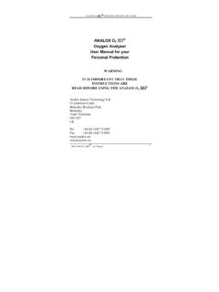
10 Please note that for solid-state and catalytic sensors, all potentiometers are factoryset. The only potentiometers that need periodic adjustments are the SPAN and ZERO potentiometers. DO NOT ADJUSTANY POTENTIOMETERS COVERED WITH A PLASTIC CAP UNLESS INSTRUCTED TO DO SO BY IST. Solid-State Sensor Catalytic Sensor Type I & II Electrochemical SensorTO SENSORPins 1 and 3are test pointsfor HeaterVoltageTB1JP1 Don t Touch(Factory Adjusted)HEATERZEROSPANTB2123TP2 TEST POINTS( to Volts)TP1321 GROUNDSIGNAL14-24 VDCTO SENSORPins 1 and 3 are testpoints for HeaterVoltageDon t Touch(Factory Adjusted)TB1 Pin 1 ZEROHEATERTP1TP2 TEST POINTS( to Volts)SPANTB214-24 VDCSIGNALGROUND123321 GROUNDSIGNAL14-24 VDCZEROSPANDon t Touch(Factory Adjusted)TEST POINTS( to Volts)TP1TP2TO SENSORTB23A)