Transcription of Model VCD-20 - Greenheck Fan
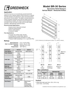
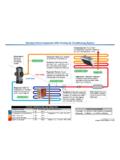
1 Installation instructions available at VCD-20 control Damper3V BladeApplicationThe VCD-20 series is a general purpose control damper for applications as an automatic control or manual balancing damper with low to medium pressure and velocity systems. A wide range of electric and pneumatic actuators are Pressure: Up to 5 in. wg ( kPa) - pressure differential Velocity: Up to 3,000 fpm ( m/s) Temperature: Up to 250 F (121 C). Consult Greenheck for higher MaterialGalvanized Steel304 SSFrame Thickness16 ga.( )12 ga.( )Frame Type5 in. x 1 in.(127mm x 25mm) ChannelSingle flange,reversed flange, double flangeBlade MaterialGalvanized Steel304 SSBlade Thickness16 ga.( )-Blade Type3V-Blade OperationOpposedParallelAxle1 2 in. dia. Plated Steel304 SSAxle BearingsSynthetic304 SSLinkage MaterialPlated Steel304 SSPaint Finishes-Baked Enamel, Epoxy, Hi Pro Polyester, Industrial EpoxyW x HMinimum SizeMaximum SizeSingle SectionMultiple SectionInches6 x 6 48 x 74 Unlimitedmm152 x 1521219 x 1880 UnlimitedSize LimitationsH*W**W & H dimension furnished approximately 1 4 in.
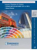
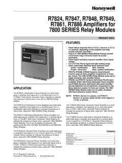
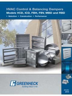
2 (6mm) undersize. Shown with optional extension pin and standoff OptionsSingle FlangeDouble FlangeReversed Flange5 1/2 in. (Typical)* Shown with optional internally mounted OperationOpposed BladesParallel Blades11/4 (typical)5 (typical)Features and Options Low profile head and sill are used on sizes less than 17 in. (432mm) high Linkage concealed in the frame Wide range of electric and pneumatic actuators. Factory installation Drop Data VCD-20 This pressure drop testing was conducted in accordance with AMCA Standard 500-D using the three configurations shown. All data has been corrected to represent standard air at a density of .075 lb/ft3( kg/m3).Actual pressure drop found in any HVAC system is a combination of many factors. This pressure drop information along with an analysis of other system influences should be used to estimate actual pressure losses for a damper installed in a given HVAC Test FiguresFigure Illustrates a fully ducted damper.
3 This configuration has the lowest pressure drop of the three test configurations because entrance and exit losses are minimized by straight duct runs upstream and downstream of the Illustrates a ducted damper exhausting air into an open area. This configuration has a lower pressure drop than Figure because entrance losses are minimized by a straight duct run upstream of the Illustrates a plenum mounted damper. This configuration has the highest pressure drop because of extremely high entrance and exit losses due to the sudden changes of area in the (W) (H) (W) (H) (W) (H) (W) (H) (W) (H) Certified Pressure Drop Data VCD-20 Velo cit y ( fpm)Pressure Drop (in . wg)Velo cit y ( fpm)Pressure Drop (in . wg)Velo cit y ( fpm)Pressure Drop (in . wg) i n.
4 X 1 2 i n. ( 305mm x 3 05mm)24 i n. x 2 4 i n. ( 610mm x 6 10mm)36 i n. x 3 6 i n. ( 914mm x 9 14mm)Velo cit y ( fpm)Pressure Drop (in . wg) i n. x 1 2 i n. ( 1219mm x 3 05mm)Velo cit y ( fpm)Pressure Drop (in . wg) in. x 48 in. ( 305mm x 1219mm)AMCA cit y ( fpm)Pressure Drop (in . wg)Velo cit y ( fpm)Pressure Drop (in . wg)Velo cit y ( fpm)Pressure Drop (in . wg) i n. x 1 2 i n. ( 305mm x 3 05mm)24 i n. x 2 4 i n. ( 610mm x 6 10mm)36 i n. x 3 6 i n. ( 914mm x 9 14mm)Velo cit y ( fpm)Pressure Drop (in . wg) i n. x 1 2 i n. ( 1219mm x 3 05mm)Velo cit y ( fpm)Pressure Drop (in . wg) in. x 48 in. ( 305mm x 1219mm)Velo cit y ( fpm)Pressure Drop (in . wg)Velo cit y ( fpm)Pressure Drop (in . wg)Velo cit y ( fpm)Pressure Drop (in.)
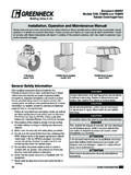
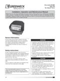
5 Wg) i n. x 1 2 i n. ( 305mm x 3 05mm)24 i n. x 2 4 i n. ( 610mm x 6 10mm)36 i n. x 3 6 i n. ( 914mm x 9 14mm)Velo cit y ( fpm)Pressure Drop (in . wg) i n. x 1 2 i n. ( 1219mm x 3 05mm)Velo cit y ( fpm)Pressure Drop (in . wg) in. x 48 in. ( 305mm x 1219mm)5D6D5DD4 (W) (H) Fan Corporation certifies that the Model VCD-20 shown herein is licensed to bear the AMCA Seal. The ratings shown are based on tests and procedures performed in accordance with AMCA Publication 511 and comply with the requirements of the AMCA Certified Ratings Programs. The AMCA Certified Ratings Seal applies to Air Performance Data Application Data2401236486074012243648 Damper Width (in.)Damper Height (in.)3000fpm2000fpm2500fpmVelocity LimitationsLeakage testing was conducted in accordance with AMCA Standard 500-D and is expressed as cfm/ft2 of damper face area.
6 All data has been corrected to represent standard air at a density of lb/ft3 ( kg/m3). 2 3 4 5 6 7 8 9 10 20 30 40 50 60 70 80 90100 150 VCD-151 2 3 4 5 6 7 8 9 10 20 30 40 50 60 70 80 90 100 150 VCD-20 Air Leakage (cfm/ft2)Air Leakage (cfm/ft2)Static Pressure Difference ( in. wg) Static Pressure Difference ( in. wg) EnvelopesOn dampers less than 18 in. (457mm) high, actuators may also require clearances above and/or below the damper frame. B and T dimensions are worst case clearance requirements for some dampers less than 18 in. (457mm) high. All damper sizes under 18 in. (457mm) high do not require these worst case clearances. If space availability above or below the damper is limited, each damper size should be individually evaluated.
7 TBDD amper frameOptionalJackshaftActuator Type/ModelHeightTBDI nches (mm)Inches (mm)AFBUP (-S) and FSNF Series, Belimo MSxx20 Series, Honeywell; 33x-2976 Series, Siemens>6 to <100123 46>10 to <18026>18006 FSLF, LF and TFB Series, Belimo>6 to <10031 26>10006 MSxx04 & MSxx09 Series, Honeywell>6 to <9043 46>9006MS75xx Series, Honeywell>6 to <100123 46>10 to <18076>1800633x-4551 Series, Siemens>6 to <10071 26>10 to <17011 26>17006331-2856, Siemens<12N/AN/AN/A>12 to <18021 29>18009 Copyright 2017 Greenheck Fan Corporation VCD-20 Rev. 15 May 2017 Multi-Section AssemblyDampers larger than the maximum single section size, will be made up of a multiple of equal size sections. Multiple section dampers can be jackshafted together so that all sections operate together as shown : dampers larger than 48 in.
8 X 74 in. (1219mm x 1880mm) are not intended to be structurally self supporting. Additional horizontal bracing is recommended to support the weight of the damper and vertical bracing should be installed as required to hold against system dampers meeting the following specifications shall be furnished and installed where shown on plans and/or as described in blades shall be 16 ga. ( ) galvanized steel 3V type with three longitudinal grooves for reinforcement. Blades shall be completely symmetrical relative to their axle pivot point, presenting identical resistance to airflow and operation in either direction through the damper (blades that are non-symmetrical relative to their axle pivot point or utilize blade stops larger than 1 2 in. [13mm] are unacceptable). Linkage shall be blade-to-blade concealed in jamb (out of the airstream) to protect linkage and reduce pressure drop and frame shall be 16 ga.
9 ( ) galvanized steel formed into a structural hat channel shape with reinforced corners to meet 11 ga. ( ) criteria. Bearings shall be corrosion resistant, permanently lubricated, synthetic (acetal) sleeve type, rotating in extruded holes in the damper frame for maximum service. Axles shall be square and positively locked into the damper Damper manufacturer s submittal data shall certify all air performance pressure drop data is licensed in accordance with the AMCA Certified Ratings Program for Test Figures , and Damper air performance data shall be developed in accordance with the latest edition of AMCA Standard manufacturer's printed application and performance data including pressure, velocity and temperature limitations shall be submitted for approval showing damper suitable for pressures to 5 in.
10 Wg. ( kPa), velocities to 3000 fpm ( m/s) and temperatures to 250 F (121 C). Testing and ratings to be in accordance with AMCA Standard of design is Greenheck 's Model Specifications1 1/4 in. (32mm) 3/4 in.(95mm)5 3/8 in.( )5 in. (127mm)Actuator7 3/4 in.(197mm)This drawing depicts the worse case clearance requirements for an actuator with a External - includes extension pin (standoff bracket optional) External kit - actuator and all mounting hardware Internal - blade lever