Transcription of Modeling Choked Flow Through an Orifice - Pipe …
1 Applied Flow Technology 2955 Professional Place, Colorado Springs, CO 80904 USA (719) 686-1000 / FAX (719) 686-1001 Modeling Choked Flow Through an Orifice Summary Periodically AFT Arrow users pose the question of what CdA value to use for Modeling Choked flow Through an Orifice . This paper reviews the subject to provide guidance in this area. As will be seen, there is not one answer. Discussion AFT Arrow provides several options in Modeling an Orifice , perhaps the two most commonly used being the Sharp-Edged and Cd (discharge coefficient) Orifice models. The Sharp-Edge model uses Idelchik's 'sharp-edged Orifice ' equation found on page 221 of reference (1); Where: w1 = velocity in upstream pipe F0, F1 = Orifice and upstream areas, respectively Idelchik lists this equation as valid for an Orifice thickness to hydraulic diameter ratio of 0 to Notably, the above relationship is for incompressible flow1 (as are all resistance coefficients in Idelchik).
2 When a Cd is specified, AFT Arrow uses the following equation from page 339 of reference (9). 1 Ref: Idelchik Page 4 footnote. + = =FFFFFFwpk Modeling Compressible Flow Through an Orifice 2 June 23 , 2010 Applied Flow Technology 2955 Professional Place, Colorado Springs, CO 80904 USA (719) 686-1000 / FAX (719) 686-1001 AFT Arrow evaluates sonic flow if a CdA is specified based on equation of Saad; For Choked flow, M = 1 and A = CdA (the same relationship is used for endpoint and expansion choking with A equaling the physical area of the pipe discharge at the endpoint or entering the expansion).
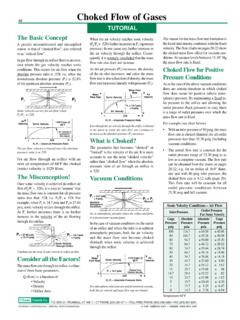
3 Crane For high Reynolds numbers from about 105 and higher, Crane, page A-20, indicates an essentially constant flow coefficient for sharp edged orifices that depends only on the Orifice to pipe diameter ratio. Cd is related to the flow coefficient C by the following: Where = Orifice diameter / upstream pipe diameter. While C increases with increasing to a value of ~ for = , because of the above relationship Cd is ~ irrespective of and this value is often used in calculating CdA by multiplying the physical Orifice area times In a related discussion on page 2-14 of ref. (3), the following equation is provided by Crane for the flow of gases and vapors: Where q is volumetric flow. This is the same form of equation used for incompressible flow with the addition of the expansion factor Y, which relates the density of the fluid at the Orifice to the upstream density.
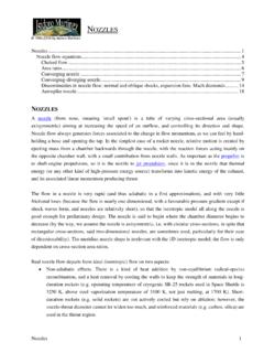
4 Further, Crane states; "When the absolute inlet pressure is greater than this amount, flow Through nozzles should be calculated as outlined on the following page." 41 =CCd PgYCAq =)144(2( )( ) + += MMRTpAmModeling Compressible Flow Through an Orifice 3 June 23 , 2010 Applied Flow Technology 2955 Professional Place, Colorado Springs, CO 80904 USA (719) 686-1000 / FAX (719) 686-1001 ..which goes on to state; "A smoothly convergent nozzle has the property of being able to deliver a compressible fluid up to the velocity of sound in its minimum cross section or throat." Values of Y as a function of the pressure drop ratio (defined as the pressure differential divided by the upstream pressure) and the expansion coefficient k, are provided on page A-21.
5 For nozzles, Y has a minimum value corresponding to Choked flow. No such minimum value of Y is provided for a square edge Orifice indicating the limitations in using the Crane method to evaluate Choked flow Through an Orifice . Cunningham In his paper Orifice Meters With Supercritical Compressible Flow, ref. (4), Cunningham states; "For a well-formed convergent nozzle, the (experimental) maximum flow ratio is essentially identical with the (theoretical) critical-pressure ratio. Evidently the occurrence of sonic velocity at the throat of the nozzle prevents flow response to changes in the discharge pressure. Contrary to the behavior of the convergent nozzle, the square-edged Orifice does not exhibit a maximum flow ratio. Rather, experiment shows that the flow rate (for constant upstream conditions) continues to increase at all pressure ratios between the critical and zero; this range is defined as the 'supercritical" range of ratios" Cunningham goes on to provide a brief description of a previous investigation by Stanton, explaining that shock disturbances were evident at all Orifice pressure ratios below critical, but that the location of the critical pressure was downstream of the Orifice and moves toward the Orifice as the discharge pressure is lowered.
6 The bulk of Cunningham's paper reports on the empirically determined expansion coefficient to be used in the "ASME Equation"; pgKYAGc =102 Modeling Compressible Flow Through an Orifice 4 June 23 , 2010 Applied Flow Technology 2955 Professional Place, Colorado Springs, CO 80904 USA (719) 686-1000 / FAX (719) 686-1001 Two sets of equations for the expansion coefficient are developed. One for "flange taps" and another for "pipe taps". Each set consists of two equations, one for high pressure ratios and the other for lower pressure ratios as follows (r = P2/P1 or Pdownstream/Pupstream); Pipe taps - r >= ()() r +++ r < ()rY Flange taps - r >= () r + r < ()rY Driskell In a discussion of flow Through nozzles, restrictions and enlargements at , ref.
7 (5), reference is made to Driskell as follows; "Driskell repeated his stand in a later publication, Control-Valve Selection and Sizing. He described Choked flow as being that condition where flow cannot be increased by lowering downstream pressure. He further described the vena contracta as migrating upstream to coincide with the Orifice when the flow is completely ' Choked ' (meaning it has reached its maximum steady-state value of flow)." This appears to be both similar to and contradict Cunningham, for while a description of a moving vena contracta based on the downstream pressure is provided, it also states the vena contracta 'coincides' with the Orifice when it is ' Choked '. Contrary to this, Stanton's data (included in Cunningham's paper), clearly shows that while the vena contracta approaches the Orifice with decreasing downstream pressure it never reaches it.
8 Further, if the vena contracta 'coincides' with the Orifice as Driskell asserts, this would imply a Cd equal to , a seeming contradiction to accepted values of Cd less than for 'well formed' nozzles. Modeling Compressible Flow Through an Orifice 5 June 23 , 2010 Applied Flow Technology 2955 Professional Place, Colorado Springs, CO 80904 USA (719) 686-1000 / FAX (719) 686-1001 ENGSoft That an Orifice does not exhibit a maximum flow at a critical pressure ratio is reflected in other sources as well. For example, ENGSoft Inc. which states on their website , ref. (6); "In case of Orifice , actually there is no critical pressure. The mass flow rate increases as much as the discharge pressure is decreased till zero absolute pressure.
9 " Ward-Smith Optimal Systems, , ref. (7), provides a description of a series of experiments conducted by Ward-Smith wherein it is stated; In summary, the principal parameter affecting sonic discharge coefficient is the aspect ratio of the Orifice , expressed as the ratio of the plate thickness to the Orifice diameter (t/d).. Once sonic velocity has been achieved, further reduction of the downstream pressure cannot further increase the velocity Through the vena contracta, but if the Orifice plate is thin, it can increase the vena contracta's size. Further reductions in downstream pressure cause the vena contracta to move upstream and to consequently increase in area. Ultimately, at high pressure ratios, the vena contracta can reach the upstream edge of the Orifice , when its area would equal that of the Orifice and the discharge coefficient would be unity.
10 " Like Driskell, the vena contracta is described as reaching the Orifice at 'high' pressure ratios (indeed, the upstream edge of the Orifice ) yielding a discharge coefficient of Ward-Smith is further quoted on this subject in as providing the following Choked flow Cd values: sharp edge, t/d= 0, Cd = thin plate (0<t/d<1)Cd varies smoothly from 1 to as function of t/d. thick plate ( 1<t/d<7) Cd = constant very thick plate (t/d > 7) Cd less than per Fanno friction Where t/d equals the ratio of the Orifice thickness to its diameter. Modeling Compressible Flow Through an Orifice 6 June 23 , 2010 Applied Flow Technology 2955 Professional Place, Colorado Springs, CO 80904 USA (719) 686-1000 / FAX (719) 686-1001 ASME Finally, we have the current ASME standard MFC-3M-1989.