Transcription of MODELS HSJ HS1 HS2 - Tjernlund
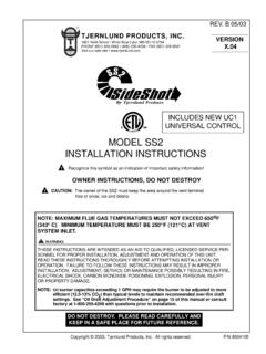
1 Copyright 2002, Tjernlund Products, Inc. All rights 8504106 REV. 08/02 OWNER instructions , DO NOT DESTROYR ecognize this symbol as an indication of important Safety Information!NOTE:FLUE GAS TEMPERATURES MUST NOT EXCEED 600 OFAT VENT SYSTEM INLET FOR INSTALLATIONSAND 285OC (550OF)AT VENT SYSTEM INLET FOR CANADIAN INSTALLATIONS. THESE instructions ARE INTENDED AS AN AID TO QUALIFIED, LICENSEDSERVICE PERSONNEL FOR PROPER INSTALLATION, ADJUSTMENT AND OPERA-TION OF THIS UNIT. READ THESE instructions THOROUGHLY BEFOREATTEMPTING INSTALLATION OR OPERATION.
2 FAILURE TO FOLLOW THESEINSTRUCTIONS MAY RESULT IN IMPROPER INSTALLATION, ADJUSTMENT, SER-VICE OR MAINTENANCE POSSIBLY RESULTING IN FIRE, ELECTRICAL SHOCK,CARBON MONOXIDE POISONING, EXPLOSION, OR PERSONAL INJURY ORPROPERTY DAMAGE.!DO NOT DESTROY. PLEASE READ CAREFULLY AND KEEPIN A SAFE PLACE ON JOB SITE FOR FUTURE HS1 HS2 FOR NATURAL GAS, LP OR OILTJERNLUND PRODUCTS, Ninth Street White Bear Lake, MN 55110-6794 PHONE (800) 255-4208 (651) 426-2993 FAX (651) 426-9547 Visit our web site NEW UC1 UNIVERSAL CONTROLVERSION OREARLIERA ddress all correspondence to:Customer Service Tjernlund Products, Inc.
3 1601 Ninth Street White Bear Lake, MN 55110-6794 Call us toll free at 800-255-4208, visit our web site @ or email us at OF CONTENTSPAGE(S)SIZING TABLES AND SPECIFICATIONS .. 1 - 2 INSTALLATION RESTRICTIONS .. 2 CAUTIONS .. 2 - 3 GENERAL 3 SAFETY INSPECTION OF PREVIOUSLY USED APPLIANCE INSTALLATION .. 3UC1 UNIVERSAL CONTROL BOARD FEATURES ..4 LED STATUS & FAULT / POST-PURGE & PROVER STATUS CHECK SETTINGS ..5 INSTALLATION .. 6 VENT SYSTEM TERMINATION INSTALLATIONS .. 6 VENT SYSTEM TERMINATION CANADIAN INSTALLATIONS .. 7 POWER VENTER INSTALLATION.
4 7 CODE REQUIREMENTS ..7 INSTALLATION 8 POWER VENTER 9 DRAFT CONTROL INSTALLATION ON AN INDUCED DRAFT GAS APPLIANCE .. 9 - 10UC1 UNIVERSAL CONTROL INSTALLATION .. 10 ELECTRICAL WIRING ..10 WARNINGS, SEQUENCE OF OPERATION & INTERNAL SCHEMATIC ..10 - 11UC1 WIRING CONNECTIONS TO VENTER GROUND, MOTOR AND PROVER LEADS ..11 MULTIPLE OR MILLIVOLT APPLIANCE INTERLOCKS ..11UC1 WIRING TO GAS FIRED APPLIANCE ..12 - 14UC1 WIRING TO OIL FIRED EQUIPMENT ..14 -16UC1 OPERATION CHECK, DRAFT CHECK, SAFETY INTERLOCK / COMBUSTION AIR TEST ..16 - 17 MAINTENANCE.
5 18 TROUBLESHOOTING ..18 - 19 WARRANTY & REPLACEMENT PARTS ..19 VENTER SPECIFICATIONS1HS-SERIES model SELECTION TABLEPOWER VENTER DIMENSIONSIMPORTANTT able footage is based on equivalent vent pipe length. To calculateequivalent vent pipe length, add the straight vent pipe plus 10 forevery 90 Oelbow and 5 for every venting multiple appliances with one Power Venter, the total com-bined BTU/hr. input of all appliances must be added together to sizethe Power UC1 Universal Control may be interlocked with DryContact, 24 VAC or 115 VAC heater control UNIVERSAL CONTROL SPECIFICATIONSINSTALLATION device must be installed by a qualified professional installer in accordance with these instructions .
6 If improperly installed, a hazardous condition such as explosion or carbon monoxide poisoning could not install the Power Venter on incinerators, incinerating toilets, condensing type appliances or solid-fuel burning appliances. Power Venter shall only be installed on Natural Gas, LP or Oil-fired not install the Power Venter on an appliance with an automatic valve having a manual opener unless the manual opener has been rendered inoperative or the automatic valve has been replaced with a valve not equipped with a manual Power Venter may only be installed on appliances equipped with a draft hood, draft diverter or barometric draft Power Venter shall not be installed where flue gas temperatures exceed 6000F.
7 At Power Venter inlet for or 2850C (5500F) for Canadian GAS TEMPERATURE VERIFICATION:A)Consult appliance manufacturer for temperature of gases at the appliance outlet after dilution by draft hood, draft diverter or baro-metric draft ) Measure temperature of flue gases at the Power Venter inlet at time of installation. Temperature should be measured after appliance andPower Venter have operated for at least 15 minutes, allowing flue gas temperature to gas temperature at Power Venter inlet must not exceed 6000F. for or 2850C (5500F) for Canadian The appliance(s) may only be installed on the suction side of Power Venter.
8 UC1 is intended for indoor installation only. Do not mount the UC1 junction box on a heat source that exceeds 140oF. Examples of improper mounting surfaces include vent pipe, top of heater casing or any place where radiant or convective heat would cause the junction box temperature to exceed 140oF (60oC). CAUTIONSThe Power Venter must be installed by a qualified installer in accordance with these instructions and all local codes or in theirabsence in accordance with the latest edition of The National Fuel Gas Code (ANSI #54), NFPA # 31 Oil BurningEquipment, the latest edition of the National Electrical Code (NFPA#70) and the Occupational Safety and Health Act (OSHA) whenapplicable.
9 Canadian installations must comply with The Natural Gas Installation Code ( ); Propane InstallationCode ( ); Installation Code For Oil Burning Equipment (CAN/CSA-B139). Improper installation can create a haz-ardous condition such as an explosion, fire, electrical shock or carbon monoxide poisoning resulting in property damage, personalinjury or death. Qualified Installer shall mean an individual properly trained and licensed in accordance with local installation, adjustment, alterations, service or maintenance can cause injury or property damage.
10 Refer to this assistance or additional information consult a qualified installer, service agency, gas or oil SWITCHINGCAPACITYJ1 / J2 JUMPERSAFETYCIRCUITADD VENTER MOTORLOAD PLUS 1/2 AMPFOR UC1 LOADEXTERNALCALL TRIGGERMETHODSJ1 / J2P1 / P2L / N3 TO 4T-BLOCKT-BLOCK(RELAY K1)XL / XNUC1 CONTROLM & MTR(RELAY K2)T-BLOCKA / B24V1 / 2115V1 / 2 ORORUSED TO JUMP CALL HOT (24 VAC) OR CALL LINE (115 VAC) FROM TERMINAL 1 TO TERMINAL TO FAN mA @ 5 VDC. DO NOT SUPPLY POWER J1-J2 JUMPER IF A DIFFERENT VOLTAGE SOURCE IS PROVIDED TO TERMINAL VAC 10 %, 50/60 HzMOTOR - 1 MAX.