Transcription of MOMENT DISTRIBUTION METHOD - FREE STUDY
1 MOMENT DISTRIBUTION METHOD . This is a stand-alone' tutorial for students studying structures. It is about a METHOD of finding the bending MOMENT in beams that cannot easily be solved by other methods . The theory is due to the work of Professor Hardy Cross - the very same man who evolved the theory for solving pipe networks. The work can be used to solve the bending MOMENT in frames but this is not covered here. At the heart of this METHOD is a way to determine how a MOMENT M. applied at a rigid joint (such as that shown) is distributed to the members. When the MOMENT is applied the joint will rotate a tiny angle and this is the same for all the members at the joint and leads to the solution.
2 The fraction of M that is distributed to any given member is KDM where KD is called the DISTRIBUTION factor. The fraction depends on the rotational stiffness K of each member and this depends on:- 1. The length, material and cross section (E, I and L). 2. The way the other end of the member is fixed. A fraction of M is also carried over to the opposite end of the member and this depends on the way the end is supported. The MOMENT carried over to the other end is KC KD M where KC is the carry over factor. Usually we use Mx = KC My where My is the MOMENT at the joint end and Mx the MOMENT at the other end.
3 ROTATIONAL STIFFNESS K. Click here for the full derivation ROTATIONAL STIFFNESS. M. Relative Rotational Stiffness K for each member is the ratio K = where M is the MOMENT in the . member at the joint. M 4EI. When the other end of the member is rigidly fixed =K= . ( at end B of AB). L. M 3EI. When the other end is simply supported = K = . ( at end B of CB). L. At a free end ( C on the diagram) the stiffness is zero as there is no MOMENT M = 0. At a rigid end (wall) ( A on the diagram) the stiffness is infinity since = 0. 2009 1. MOMENT DISTRIBUTION FACTOR.
4 Click here for the derivation DISTRIBUTION FACTOR. The MOMENT M applied at the joint is distributed to the members in a proportion that depends on the stiffness of the member as seen from the joint. The MOMENT distributed to each member at joint B is MBA, MBC and MBD. At the joint the sum of all the moments is zero so it follows MBA + MBC + MBD = M. The proportion of M distributed to a member is called the DISTRIBUTION FACTOR which we will designate KD. MBA = (KD) BAM MBC = (KD) BCM MBD = (KD) BDM. At a free end KD = 1 and at a rigidly fixed end KD = 0. CARRY OVER FACTOR.
5 When a portion of M is distributed to a member, a MOMENT is produced at the opposite end of the member. The proportion of M at the opposite end is called the CARRY OVER FACTOR and we will define it as KC. MOMENT carried over = KC x M at A the MOMENT is MA = (KC)A x MB. The derivation shows that when the other end is rigidly fixed KC = of the MOMENT at the joint end. When the other end is simply supported KC = 0 (no MOMENT possible at a simple support or pin joint). 2009 2. APPLICATION TO BEAMS. The MOMENT DISTRIBUTION METHOD may be used to solve difficult problems that cannot be solved by other means because there are too many unknowns (Indeterminate beam or structure).
6 In this tutorial we will only STUDY beams with joints such as the one shown. The beam is rigidly held at the wall C. and simply supported at A and B. There will be three vertical reactions due to the point load F and the uniform load w. These are too many unknowns to solve by normal means. We start be treating the beam as two parts AB and BC. It might be that the lengths AB and BC have a different flexural stiffness EI and this can be accommodated in this METHOD . Next we clamp the end of each section rigidly so there is no deflection or rotation. This enables us to tackle each section separately to begin.
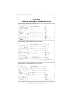
7 When a joint is fixed there must be a fixing MOMENT at each end MA, MB and MC. Fb 2a Fa 2 b It can be shown that for a single point load F M A = 2 and M B = 2. L L. 2. wL wL2. And for a single uniformly distributed load w MA = and M B = . 12 12. In this analysis, clockwise is positive and anticlockwise is negative which is consistent with the other tutorials in the series where x is measured from the left and an upwards force causes sagging which is always positive. For any other combination of loading, the principle of superposition may be used. This principle allows us to calculate the moments for each load separately and then add them together for the combined affect.
8 Click here for the derivation FIXING MOMENT . Since the joints are not in reality rigidly fixed, we now consider what happens if we release the fixing clamps and restore the beam to its correct condition. The beam would take up its natural position. In this example, the MOMENT at A must be zero because it is a free end so a MOMENT equal and opposite of MA must be added and distributed at A. There will be a carry over to end B and we should take this into consideration before balancing the joint B. Joint C is rigid so we do not need to add a balancing MOMENT and there is nothing to distribute.
9 We calculate the imbalance at B and add an equal and opposite MOMENT to balance it and then distribute it. This would equalise the MOMENT at B but a fraction of the MOMENT is carried over to the ends and this upsets the balance again so we have to redistribute the MOMENT again and again until the MOMENT at a joint is balanced. A worked example will explain it better. 2009 3. WORKED EXAMPLE No. 1. Find the bending MOMENT at A, B and C for the beam shown. The EI values are the same for both sections. First treat the beam as two separate sections with rigid ends.
10 CALCULATE FIXING MOMENTS and STIFFNESS FACTORS. Fb 2a 150 x 103 x 12 x 1. MEMBER AB MA = 2 = = x 103. L 22. Fa 2 b 150 x 103 x 12 x 1. MB = 2 = 2. = x 103. L 2. Note that MB and MB are equal and opposite only because F is in the middle. 3EI 3EI. K BA = = = L 2. wL2 15x103 x32. MEMBER CB MB = = = x 103. 12 12. 2. wL 4EI 4EI. MC = = x 103 K BC = = = 12 L 3. CALCULATE THE DISTRIBUTION FACTORS. K At end B of BA KD = BA = = 4. K K BC At end B of BC KD = = = K Note 1 is another way to get it. Calculate the CARRY OVER FACTOR. When a balancing MOMENT is applied at a point, of the MOMENT is carried over to the opposite end unless the opposite end is free in which case it is zero.