Transcription of Monitoring of Power Transformer Winding Temperature …
1 Monitoring of Power Transformer Winding TemperatureUsing robust Fiber Optic Sensing SystemABSTRACTD irect measurement of actual Transformer Winding Temperature using fiber optic thermometry has been increasing sincethe mid-1980s due to the growing need to accurately monitor the Power Transformer hot spot, predict load levels, andimprove capacity utilization. While early fiber optic instruments and probes were delicate, resulting in unacceptablyhigh failure rates, the development over the past decade of improved, ruggedized probe designs, in particular, havegreatly reduced the likelihood of fiber damage during installation and enhanced the ease of installation. In addition,nearly twenty years of operation on hundreds of transformers deployed in the field, have demonstrated both the indus-trial robustness of the technology and the value to be gained from direct measurement of the hot spot Temperature . Thispaper will discuss the current state-of-the art in systems and rugged probe DIRECT HOT SPOT Monitoring OF TRANSFORMERSFor many metropolitan utilities, the advent of deregulation and the increasing environmental opposition to construc-tion of new high voltage Power lines has greatly taxed the existing transmission and distribution (T&D) key to being able to balance fluctuations in Power load and demand against increasingly tight capacity in the T&Dinfrastructure often rests in the ability of the utility to make intelligent decisions about Transformer loading.
2 This inturn is highly dependent on knowing both the location and Winding Temperature of the Transformer s hot conventional Winding Temperature indicator (WTI), still widely used in the industry, is designed to simulate thethermal behavior of the hottest portion of the Winding . This is done by passing a known portion of the load currentthrough a resistive element in the indicator, which is located at a point remote from the high voltage regions of thetransformer in the bulk oil(1,2). Unfortunately, it has been proven that thermal modeling can result in large discrepan-cies between the simulated data and the true Winding Temperature , as well as a time delay of four to five hours. Whileperhaps acceptable for normal loading conditions, this can result in serious damage to the Transformer or degradationof lifetime, when the Transformer is operated at closer to peak rated or even over peak rated conditions, sometimesrequired in an overcome this limitation, in the early 1980 s EPRI became interested in directly measuring and Monitoring hot spottemperature of Transformer windings and funded a project to evaluate Luxtron s first generation Fluoroptic thermome-ter.
3 General Electric Company performed the evaluation as part of an ongoing study of Transformer aging (3). Based onthe results of this evaluation it was concluded that the fiber optic sensing technology met the general requirements ofthe Transformer application, although certain improvements were still required for reliable long term Monitoring . Thedata indicated that the Transformer had substantial excess capacity available for emergency use if loading were based ondirect Winding Temperature measurement(4).EVOLUTION OF RUGGEDIZED FIBER OPTIC HOT SPOT Monitoring SYSTEMSIn the mid-1980 s, Luxtron developed a second generation fiber optic thermometry system(5)that addressed many ofthe issues encountered in the field with the first generation product. While significant improvement was made in thearea of long-term reliability, the high cost and the need to replace key components in the system ( the light source)over the normal life of the Transformer , were still considered unacceptable by many the early 1990 s, Luxtron developed a more robust , lower cost, third generation system (WTS-11).
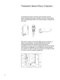
4 Most notably,this system replaced the limited life halogen flash lamp light source with long life LEDs. In addition, a new ruggedi-zed probe, designed specifically to minimize breakage during installation was 2001, in response to feedback from key utilities, Luxtron developed a fourth generation system (WTS-22). In addi-tion to the ability to monitor Temperature , this fourth generation system has built-in control capability to allow auto-mated control of relays and indication of the progress made in the development of industrially robust fiber optic hot spot Monitoring sys-tems, is the 10-year warranty carried by the fourth generation OPTIC HOT SPOT Monitoring TECHNOLOGYThe Luxtron Fluoroptic technology measures the decay time of a inorganic (ceramic) photoluminescent sensor materi-al ( a phosphor ). The phosphor sensor is attached to the end of a quartz fiber, which is cabled with Teflon sheathto ensure high dielectric integrity. The sensor is subjected to excitation by a light pulse, generated by a high intensityLED at the appropriate wavelength, which produces hundred of pulses per second.
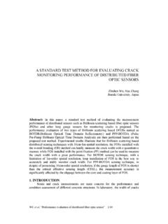
5 The measured Temperature is a time domain, intensity inde-pendent, property of the phosphor. The samples are averagedand curve fitted for the calculation of decay time (Figure 1).The decay time of the phosphor changes predictably andrepeatably with change in Temperature of the sensor. A cal-ibration table correlates the measured decay time to temper-ature (Figure 2).Because the measurement is an intensity independent, inher-ently stableproperty of the phosphor, this makes Luxtron sFluoroptic technology particularly well suited to industrialtransformer applications vs. alternative fiber optic technolo-gies ( semiconductor adsorption-edge, Fabry-Perot) onseveral dimensions:No calibration or long-term drift:Fluoroptic systems are not subject to long term drift and therefore do not requireperiodic calibration. This is a major virtue when applied to hot spot Monitoring systems mounted on transformersthat are often found in isolated geographic locations.
6 Also, since the sensors are passive in nature, reliable meas-urements can be made at any time during the life of the trans-former as long as the fiber remains intact. Other technologiesare intensity dependent; calibration shift can occur as the lightsource independent of instrument:Fluoroptic probes can bemixed and matched with different instruments and still achievehigh precision measurements. This allows the Winding sensorsto be pre-installed during Transformer construction and aninstrument to be connected at a later time. Other technologiesrequire probes and instruments to be calibrated together toachieve a comparable degree of 40 80 120 160 200T (mSec) Temperature (oC)Figure 1 Plot representation of method for extracting decay timeFigure 2 Calibration table correlating decay timeto temperatureAbility to use long life light sources:Fluoroptic systems use LED light sourcesdesigned for industrial applications withits virtually unlimited life.
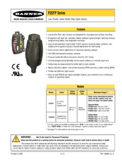
7 Other fiberoptic technologies require the use of abroadband light source such as an incan-descent or halogen light bulb that havetypical lifetime ratings of 1 a light bulb in the field can beproblematic given the geographically iso-lated location of many transformers . Also,replacing a light bulb requires properremounting in the optical assembly and re-calibration with sophisticated photometricequipment, normally necessitating returnof the instrument to the probe tip is generally attached to the Transformer Winding via a horizontal spacer. Probes can be of variable lengths(most commonly 4 and 6 meters) depending on the sensor location and the size of the Transformer . The other end of theprobe fiber is routed to a tank wall feed-through connector. An outdoor extension cable is connected to the other side ofthe feed-through, which carries the signal from the probe to the instrument where the data are processed (Figure 3).
8 Theinstrument may have multiple channels. A standard unit consists of 1 to 4 channels. Measurements from all channels canbe updated PROBE DESIGNThe probe consists of a small sensor tip about 1 mm in diameter, as shown in figure 4. The tip is adhered to one end ofthe fiber and encapsulated with a layer of Teflon FPA. An additional protective Teflon layer is placed over the encap-sulation to ensure complete protection of the tip from mechanical and Transformer oil damage. The fiber itself is alsodouble-jacketed with Teflon PFA. The outer jacket is perforated along the length of the fiber to allow oil to penetrateinto the air space between the out and the inner jacket. The other end of the fiber is terminated with an SMA connec-tor for connection to the feed through at the tanks worked extensively with trans-former manufacturers to improve ease ofinstallation and reduce susceptibility toprobe breakage during installation. Themost common cause of probe breakageduring installation was the fiber being benttoo sharply or pulled into a knot.
9 Onemajor improvement made over the pastdecade has been to increase the flexibilityof the fiber by reducing the fiber core sizeto 200 micrometers. This greatly reducedthe incidence of breakage during installa-tion by reducing the fiber bend radius to 2 to 3 millimeters. A second key improvement was to add a white, thick-walledTeflon spiral wrap to the outside of the double Teflon-jacketed probe. This greatly improved the impact resistance ofthe fiber to tools or heavy equipment being accidentally rolled over it and also prevents the fiber from being bentsharply. The white color also improved visibility. Open Helix Teflon ArmorJam NutCoupling SleeveViton O-RingTeflon PFAK evlarCeramic TubePhosphor SensorAll-Silica FiberSilicone SealantTip DetailFigure 4 Rugged Transformer probe with spiral wrap and probe tip detailFiberoptic ProbeST Connector31 Adapter Plate2 Tank Wall Feedthrough4 External Fiberoptic Extension CableXfmr WallOutside TransformerInside TransformerTo InstrumentFigure 3 Fiber optic hardware assembly, from probe to outdoor extension drawing of the current ruggedized probe is shown in figure 4.
10 Probes, made with the ruggedized design, have beenextensively tested for their improved mechanical strength as well as their retained dielectric strength. The table belowsummarized the test data of the ruggedized versus non-ruggedized (old) TEST DATASENSOR INSTALLATION METHODSThe sensor can be placed in thermal contact with the Winding in a variety of ways. The most common technique is toimplant the sensor in a horizontal spacer of the type designed to hold the conductors apart in the assembled transformerso as to leave space for oil flow. The spacer technique allows convenient placement and also provides crush protectionfor the fiber probes. Three types of spacer materials have been used: Nomex, cardboard and Gortex. Tests at EHVW eidmann have shown no fiber damage at pressures of up to 3000 psi(6) using a Nomex spacer. Nylon tubing can alsobe used to guide the sensor to its intended location after the Transformer is complete. The sensor can also be taped tothe conductor using the insulating paper, which is wrapped around the tank wall penetrator has tapered pipe threads (see Figure 3).