Transcription of MINI-BEAM DC Voltage Series Sensor - Banner Engineering
1 Quick Start GuideSelf-contained photoelectric sensorsSensor FeaturesGain (Sensitivity) Adjustment ScrewAlignment Indicator Device (AID)*Light/Dark Operate Select SwitchClockwise: Light Operate (outputs conduct when sensing light is received).Counterclockwise: Dark Operate (outputs conduct when sensing light is not received).* Patent no. 4356393 WARNING: Not To Be Used for PersonnelProtectionNever use this device as a sensing device forpersonnel protection. Doing so could lead toserious injury or death. This device does notinclude the self-checking redundant circuitrynecessary to allow its use in personnel safetyapplications. A Sensor failure or malfunction cancause either an energized or de-energized sensoroutput 2 m ( ft) unterminated cable models are listed.
2 To order the 9 m (30 ft) PVC cable model, add the suffix "W/30" to the cabled model number. For example, SM31EW/30. To order the 4-pin M12/Euro-style QD models, add the suffix QD to the model number. For example, SM31 EQD. To order the 150 mm (6 in) cable with QD, add the suffix QDP to the model number. For example, SM31 EQDP. To order a ms response time model, add the suffix MHS to the model number. For example, ModeRangeLEDM odelOPPOSEDO pposed Emitter3 m (10 ft)Infrared, 880 nmSM31 EOpposed ReceiverSM31 ROpposed Emitter - Long Range30 m (100 ft)SM31 ELOpposed Receiver - Long RangeSM31 RLOPPOSEDO pposed Emitter - Clear Plastic Detection0 to 300 mm (0 to 12 in) Actual range varies,depending on the light transmissionproperties of the plastic material red, 650 nmSM31 EPDO pposed Receiver - Clear Plastic DetectionSM31 RPDRETRONon-Polarized Retroreflective5 m (15 ft)SM312 LVPPOLAR RETROP olarized Retroreflective55 mm to 2 m (2 in to 7 ft)SM312 LVAGE xtended-Range Polarized Retroreflective10 mm to 3 m ( in to 10 ft)SM312 LPDIFFUSED iffuse380 mm (15 in)
3 Infrared, 880 nmSM312D300 mm (12 in)SM312 DBZD ivergent Diffuse130 mm (5 in)SM312 WCONVERGENTC onvergent16 mm ( in) FocusSM312C43 mm ( in) FocusSM312C2 MINI-BEAM DC Voltage Series Original Document69943 Rev. F26 January 201869943 Sensing ModeRangeLEDM odelCONVERGENT16 mm ( in) FocusVisible red, 650 nmSM312CV43 mm ( in) FocusSM312CV2 CONVERGENT16 mm ( in) FocusVisible blue, 475 nmSM312 CVB49 mm ( in) FocusSM312CV2 BCONVERGENT16 mm ( in) FocusVisible green, 525 nmSM312 CVG49 mm ( in) FocusSM312CV2 GGLASS FIBERG lass Fiber OpticRange varies, depending on sensing modeand fiber optics , 880 nmSM312 FVisible red, 650 nmSM312 FVVisible blue, 475 nmSM312 FVBV isible green, 525 nmSM312 FVGPLASTIC FIBERP lastic Fiber OpticVisible red, 650 nmSM312 FPVisible blue, 475 nmSM312 FPBV isible green, 525 nmSM312 FPGS pecial High-Power Option Plastic FiberOpticVisible red, 650 nmSM312 FPHW iring DiagramsEmitters with Attached CableAll Other Models with Attached Cablebnbu+ 10-30V dcbnwhbu+ bkLoadLoad10-30V dcEmitters with Quick Disconnect (4-pin Euro-Style)All Other Models with Quick Disconnect (4-pin Euro-Style)
4 Bnwhbu+ bk10-30V dcbnwhbu+ bkLoadLoad10-30V dcThe output type for all models is Bipolar NPN/PNP; load 150 mA max., each Mounting and AlignmentMINI- beam sensors perform most reliably if they are properly aligned and securely maximum mechanical stability, mount MINI-BEAM sensors through 18 mm diameter holes by their threaded barrel (whereavailable), or use a mounting bracket. A complete selection of mounting brackets is available. Visit or contact Banner Engineering for information on mounting with line-of-sight positioning of the MINI-BEAM Sensor to its emitter (opposed-mode sensing) or to its target (all othersensing modes). When using a retroreflective Sensor , the target is the retroreflector ( retro target ).
5 For diffuse or convergentsensing modes, the target is the object to be detected. MINI-BEAM DC Voltage - Tel: +1-763-544-3164P/N 69943 Rev. FApply power to the Sensor (and to the emitter, if using the opposed mode). Advance the 15-turn Gain control to maximum(clockwise end of rotation) using a small flat-blade screwdriver. The Gain control is clutched at both ends to avoid damage and will free-wheel when either endpoint is the MINI-BEAM Sensor is receiving its light signal, the red LED Alignment indicator will be ON and flashing at a rate proportionalto the signal strength (faster = more signal). Move the Sensor (or retro target, if applicable) up-down-right-left (including angularrotation) to find the center of the movement zone within which the LED indicator remains ON.
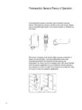
6 Reducing the Gain setting reducesthe size of the movement zone for more precise the alignment motions after each Gain reduction. When optimum alignment is achieved, mount Sensor (s) (and the retrotarget, if applicable) solidly in that position. Increase the Gain to the Sensor by placing the object to be detected in the sensing position, then removing it. The Alignment indicator LED shouldcome ON when the sensing beam is established (Light condition) or be ON when the beam is broken (Dark condition). If theAlignment indicator LED stays ON for both sensing conditions, consider the following tips for each sensing Mode AlignmentObjectEmitterReceiver Flooding occurs when a portion of the sensing beam passesaround the object to be sensed.
7 Burn-through occurs when aportion of the emitter s light energy passes through a thin ortranslucent object, and is sensed by the correct either problem, do one or more of the following toreduce the light energy: Reduce the Gain adjustment on the receiver Add an aperture to one or both lenses ( MINI-BEAM apertures, available from Banner , fit neatly inside thelens assembly) Intentionally misalign the emitter and receiverNote: Light condition: Sensor output isON when there is no object in thebeam Dark condition: Sensor output is ONwhen there is an object in the beamDiffuse Mode AlignmentObjectIf the Alignment LED does not go OFF when the object isremoved from the beam , the Sensor is probably detecting lightreflected from some background object.
8 To remedy thisproblem: Reduce the reflectivity of the background by paintingthe surface(s) flat-black, scuffing any shiny surface, ordrilling a large hole, directly opposite the diffuse Sensor Move the Sensor closer to the object to be detectedand reduce the Gain adjustment. Rule of thumb fordiffuse sensing: The distance to the nearestbackground object should be at least three times thesensing distanceNote: Light condition: Sensor output isON when there is no object in thebeam Dark condition: Sensor output is ONwhen there is an object in the beamMINI- beam DC Voltage Series P/N 69943 Rev. - Tel: +1-763-544-31643 Retroreflective Mode AlignmentRetroTargetA highly reflective object may reflect enough light back to aretroreflective Sensor to allow that object to slip through thebeam, without being detected.
9 This problem is called proxing, and the following methods may be used to correct it: Position the Sensor and retro target so the beam willnot strike a shiny surface perpendicular to the sensorlens Reduce the Gain adjustment Add a polarizing filter (for model SM312LV)Note: Light condition: Sensor output isON when there is no object in thebeam Dark condition: Sensor output is ONwhen there is an object in the beamConvergent Mode AlignmentObjectLow Reflectivity BackgroundThe sensing energy of a convergent mode Sensor isconcentrated at the specified focus point. Convergent modesensors are less sensitive to background reflections, comparedwith diffuse mode sensors. However, if background reflectionsare a problem: Skew the Sensor position at a 10 to 25 angle toeliminate direct reflections from shiny backgroundsurfaces Reduce the reflectivity of the background by paintingthe surface(s) flat-black, scuffing any shiny surface, ordrilling a large hole, directly opposite the Sensor Reduce the Gain adjustmentNote: Light condition: Sensor output isON when there is no object in thebeam Dark condition: Sensor output is ONwhen there is an object in the beamPlastic Fiber InstallationTrimmed fibercontrol endsPlastic fiberemitter portPlastic fiberreceiver portGripperUnlockLockAdapters and fibersSensor Face1.
10 With supplied fiber cutter, make a clean cut at the controlends of Unlock the fiber gripper as shown in the Apply appropriate fiber adaptors to the fiber, if Gently insert the prepared fiber ends into the ports as far asthey will Slide the fiber gripper back to lock, as shown in the drawing. MINI-BEAM DC Voltage - Tel: +1-763-544-3164P/N 69943 Rev. FGlass Fiber InstallationO-ringRetaining Clip1. Install the O-ring (supplied with the fiber) on each fiber end, as shown inthe While pressing the fiber ends firmly into the ports on the Sensor front,slide the U-shaped retaining clip (supplied with the Sensor ) into the slotin the Sensor 's barrel, until it snaps into Voltage and Current10 to 30 V dc (10% maximum ripple) at less than 25 mA (exclusive of load)Supply Protection CircuitryProtected against reverse polarity and transient voltagesOutput ConfigurationBipolar.