Transcription of MOSLEY Trap Master Version MODEL TA-33-M 2011 - …
1 SERIAL # The high performance of your MOSLEY antenna can only be achieved if the antenna is assembled in accordance with the instructions supplied. Substitution of materials or modification of design will materially lessen this performance. MOSLEY Trap Master MODEL TA-33-M * TA-33-M Two Section Boom * TA-33-MSP Three Section MIL Boom Assembly Instructions For assistance with assembly contact: MOSLEY Electronics, Inc. Technical Support 636-583-8595 Version A S S E M B L Y I N S T R U C T I O NS F O R MOSLEY TRAP Master MODEL TA-33-M Specifications Frequency, MHz 28, 21, 14 Power Rating, watts CW 1500 Power Rating, watts SSB 2500 Power Rating, AM/FM 600 Power Rating, RTTY/AMTOR 600 VSWR at frequency to Forward Gain, dBd 10 meters Forward Gain, dBd 15 meters Forward Gain, dBd 20 meters Front-to-Back Ratio, dB 10 meters 20 Front-to-Back Ratio, dB 15 meters 20 Front-to-Back Ratio, dB 20 meters 20 Boom Length 14 ft m Maximum Element Length 28 ft m Turing Radius ft m Mast Size hardware (equipped) in cm Assembled weight 37 lbs kg Wind Surface Area sq ft.
2 530 sq m Wind Load, EIA Standard 80 MPH 114 lbs kg Warranty 2 Recommended Coax Belden RG-8 / RG-213 Options (E-mail for details.) 12, 17, 30, 40 Meters Options (E-mail for details.) Convert to 4 Elements MOSLEY Electronics, Inc. 1325 Style Master Drive Union, Missouri 63084 Phone 636-583-8595 Fax 636-583-0890 Table of ContentsSpecifications i W A RN I N G N O T I C E S Installation Warning 4 Deburring Notice 5 Coil / Trap Notice 5 Assembly Cautions 6 P A R T S L I S T Tubing 8 Traps 8 Plates & Supports 8 Hardware 9 Other Parts 9 E L E M E N T A S S E M B L Y Frequency Code Settings 10 Assembly of Driven Element 10 Assembly of Parasitic Elements 12 B O O M A S S E M B L Y Assembly of 2 Section Boom 14 Assembly of Mast Plate 15 Assembly of 3 Section Boom 16 A T T A C H I N G C O A X Preparing Coax 17 Using an RF Choke 17 F I N A L C H E C K antenna Layout 18 SWR Curves 18 S U G G E S T I O N S Checking antenna Before Final Installation 19 Watch Out for Artificial Ground 20 Use of a Balun or Not 20 Stacking
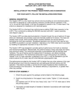
3 20 P R O D U C T S U P P O R T Technical Support 21 Warranty 21 Receipt of Shipment 22 M O S L E Y .. A B E T T E R AN T E N N A ! 4 Warning Notices Installation Warning WARNING - INSTALLATION OF THIS PRODUCT CLOSE TO ELECTRICAL POWER LINES IS DANGEROUS AND COULD BE FATAL. FOR YOUR safety AND PROTECTION, BECOME FAMILIAR WITH AND FOLLOW THE INFORMATION BELOW. Every year many people are permanently injured or killed through careless installation of communication antennas. These accidents can be avoided if proper information is obtained and simple safety precautions are observed. Antennas, such as this, are cumbersome and hard to handle after assembly. Installation of this assembly upon a supporting structure close to a power line could result in electrocution if accidental contact is made with it.
4 Choose the installation site of the antenna carefully. Determine the overall height of the complete antenna system; include the supporting structure s height (tower, slip-up mast, etc.), rotor (if needed) and the length of the antenna s longest element. The antenna system should be installed a minimum of ten feet over and above the collective height of the system itself, away from any electrical power line. If it is not possible to meet this criterion, it is suggested that professional help be obtained. Determine the location of the electrical service, which is supplied to your location. Most power lines are installed above the ground from a pole to the house; however, in some cases power lines are buried beneath the ground surface. Solicit the assistance of your electric power company.
5 Request that the electric service be shut off during installation time. It is suggested that professional help is obtained, however, if non-professional help is used, be sure installation procedure has been determined and known by all parties. Be sure that safety equipment has been provided and is used. If during installation of the antenna system it begins to fall, do not try to prevent it, let it fall. If the assembly comes in contact with a power line, do not touch it, call the electric power company for assistance. If any part of an antenna system comes in contact with an electrical service (supporting structure, guy lines, antenna , etc.), anyone that touches it will provide an electrical path directly to ground and may be electrocuted. If this happens, call for medical assistance, remove the victim using a non-conductive material (dry board, rope, dry tree limb, etc.)
6 , and apply artificial respiration. If a person comes in contact with electrical power M O S L E Y .. A B E T T E R AN T E N N A ! 5 lines, directly or indirectly, and has been electrocuted do not touch the victim yourself you too will be electrocuted. As previously stated, an assembled antenna is cumbersome and hard to handle. Install the antenna system only in good weather and under favorable conditions. Do not attempt to install an antenna during twilight hours, windy conditions or inclement weather such as rain, snow, etc. Unfavorable conditions greatly increase the chance of accidental mishap. There may be other factors that are unique only to your installation. Using good judgment and common sense may prevent a serious accident, permanent injury or even death.
7 Deburring Notice During the manufacture of this antenna there are many aluminum chips made by drilling and sawing. It is too time consuming and costly to make a one hundred percent removal of those loose chips from the finished product. We suggest you remove any loose chips from the inside and outside of parts before assembly. Especially check where the U-bolt holes go through a tubular part. Remove aluminum burrs from the inside and outside of all tubing ends with the aid of a file and small pocketknife. The removal of these burrs at the ends will make the telescoping of tubing sections easier. Trap assemblies have been cleaned one hundred percent on the inside. It is not necessary for you to disassemble these for cleaning or testing. It may be necessary for you to remove burrs from the ends of small tubing extending from both ends of the traps.
8 When doing so, be careful that aluminum chips do not get within the trap assemblies by way of the inside of the small tube at both ends of the trap Notice Inspect coil/trap assemblies for concealed damage before beginning assembly. Damage can occur through improper handling while in transit. TRAP ASSEMBLIES ONLY Slide back the trap seal to expose the terminating wire on each half of the trap assembly. Make sure the wire is intact and not damaged. Return the trap seal to cover the trap termination screw. If you find a coil/trap has been damaged, please contact the shipping company and MOSLEY immediately. Be sure to retain all packaging materials during the claims process. M O S L E Y .. A B E T T E R AN T E N N A ! 6 Assembly Cautions Make sure that before attempting to sleeve ANY of the pieces of tubing together you check to see that all tubing pieces are DEBURRED!
9 In building the antenna we have removed the majority of the burrs, however, due to the number of pieces of tubing, the cost of labor, the time consumption; some pieces may still have a few remaining burrs. Double-check the pieces before trying to put them together! The tubing MOSLEY uses is made for us and the telescoping tolerances are very close. If you would try and force a piece of tubing to sleeve, which is not deburred, it will SEIZE. If this would happen you aren't going to get them apart. This is a beautiful beam; we have put a lot of time and pride into it, take a few minutes and check the pieces. NOTE: PENATROX, ( MOSLEY Anti-Corrosion Compound) should be applied in a light layer/film between coupled sections of tubing to prevent formation of high resistance and seizing of aluminum.
10 Trap Assemblies are color coded on one end of the trap tubing. THIS COLOR-CODE MUST ALWAYS GO TOWARD THE BOOM. REVERSAL OF THE TRAPS WILL CAUSE HIGH AND OTHER MALFUNCTIONS. Mark the color-coded ends of the traps by placing masking tape on the metal trap cover and note the side and color on the trap. This will solve any problems if the color code comes off when sanding or placing the penatrox on the trap tubing. THE TRAPS CAN PHYSICALLY GO INTO THE 7/8" CONNECTING PIECE EITHER WAY, BUT WILL ONLY WORK PROPERLY WITH THE COLOR CODES TOWARD THE BOOM! The various pieces of tubing used on the antenna elements are also color coded on one end. This end always goes in toward the boom. Debur tubing and use the enclosed MOSLEY Anti-Corrosion Compound. Mount all elements on TOP SIDE of Boom!