Transcription of Motor Starter (AMPGARD) — Medium Voltage
1 Motor Starter ( ampgard ) Medium Voltage Technical Data TD02003001E New Information General Description Application .. 2 Features .. 2 Personnel Safety Features .. 3 Mechanical Non-Loadbreak Isolating Switch .. 4 Type SL 400 Ampere Vacuum Contactor Bolt-in .. 5 Type SL 400 Ampere Vacuum Contactor Stab-in .. 6 Current Limiting Fuses .. 7 Contactor-Fuse Coordination .. 8 Protection Considerations .. 9 Isolated Low Voltage Control .. 10 Bus and Optional Features .. 11 Reduced Voltage Starter and Reduced VoltageAutotransformer Starter .. 12 ampgard IT. Soft Start .. 13 Incoming Line.. 16 Potential Transformers and Fuses .. 16 Type LBS Loadbreak Switch.. 16 Technical Data Wiring Diagrams .. 19 Type SL 400 Ampere Vacuum Contactor .. 22 Type SJ 800 Ampere Vacuum Contactor .. 23 LBS Switch .. 24 Main Breaker Control Power .. 24 Starter Fuse Information .. 25 Layout Dimensions Full Voltage .. 26 Primary Reactor, Reduced Voltage .. 28 Autotransformer, Reduced Voltage .. 30 Synchronous Brush Type Mark V Solid-State.
2 32 Solid-State Squirrel Cage Starters, Reduced Voltage .. 34 Incoming Line/PT Layouts .. 37 Main and Tie LBS Switch Layouts .. 38 Main Breaker ampgard Dimensions.. 40 2 EATON CORPORATION Cutler-Hammer Motor Starter ( ampgard ) Technical Data TD02003001E Effective: December 2005 General DescriptionApplication The Cutler-Hammer ampgard Medium Voltage metal-enclosed control family from Eaton s electrical business provides control and protection of Medium Voltage motors and equipment rated 2300 to 6600 volts nominal/7200 volts control has a complete metal-enclosed offering: Full and reduced Voltage starting of Medium Voltage motors up to 8000 hp. Main breaker metal-enclosed switchgear, a smaller footprint, single integrated assembly direct coupled to the ampgard control. Integral LBS load break available as main, tie or feeder. The LBS can be supplied as fused or un-fused. Features Personnel safety : Positive mechanical isolating switch with visi-ble disconnect completely grounds and isolates the Starter from the line connectors with a mechanically driven isolating shutter, leaving no exposed high Voltage .
3 Medium Voltage door is mechan-ically locked closed with the disconnect; low Voltage section has separate door and is segregated from the Medium Voltage section. Ease of installation: Current limiting fuses, contactor assembly and isolating switch assembly are easily removed from the enclosure; line and load terminals are completely accessible from the front. Ease of maintenance: All components are front accessible, facilitating routine inspection and/or parts replacement. The low Voltage compartment is painted white as standard to maximize serviceability. Simplicity of design: Component-to-component design eliminates half of the electrical contactor technology: Two vacuum contactor ratings are utilized, 400 ampere and 800 ampere. 400 ampere contactors are available as stab-in or bolt-in design. 800 ampere contactors are available as stab-in design only. High degree of isolation: Main bus is located in separate com-partment on top of lineup. Vertical bus is barriered in rear of Starter and auxiliary compartments.
4 Load cables are isolated from adja-cent Starter in two-high sections. A vertical low Voltage wireway is provided for isolation of customer control wiring. The low Voltage control compartment is isolated from Medium Voltage by steel barriers. ampgard Motor Control Assembly Starter catalog types are available for the following applications: Squirrel cage, full Voltage (reversing and non-reversing). Squirrel cage, primary reactor. Squirrel cage, autotransformer. Reduced Voltage solid-state. Synchronous full Voltage . Synchronous primary reactor. Synchronous auto-transformer (reversing and non-reversing). EATON CORPORATION Cutler-Hammer Motor Starter ( ampgard ) Technical Data TD02003001E Copyright 2005 3 Personnel Safety Features One of the most important considerations in designing the Cutler-Hammer ampgard Starter was personnel safety. The result is an extensive system of interlocks and other safety features. Interlocks Interlocking on ampgard starters includes: Isolating switch mechanism locks the Medium Voltage door closed when the switch is in the ON position.
5 Provision for optional key interlocks. When door is open, interlock prevents operating handle from being moved inadvertently to ON position. When contactor is energized, isolating switch cannot be opened or closed. Other Safety Features ampgard starters include many additional features designed to protect operating personnel. These features include: Provision for a padlock on the isolating switch handle in OFF position. Shutter barrier between line terminals and isolation switch stabs is mechanically driven. Distinctive marking on back of switch assembly appears when shutter barrier is in position and Starter is completely isolated from the line. Grounding clips provide a positive grounding of the Starter and main fuses when the isolating switch is opened. High and low Voltage circuits are compartmentalized and isolated from each other. The drawout isolation switch is easily removed by loosening two bolts in the back of the switch. The shutter remains in place when the switch is withdrawn.
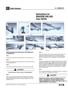
6 Isolation Switch HandleShutter Mechanism and Finger Barrier Isolation of Incoming Line Bus (Shown with Removable Portion of Isolation Switch Removed)Isolation SwitchOperating ShaftIsolation Switch Door Locking MechanismMechanical Interlock with ContactorRemovable Cover Allows Access to Bolted Line Side ConnectionsShutter Operated by Stab Motion when Isolation Switch is in PositionDistinctive Marking when Shutter is in Closed PositionMotion of Shutter 4 EATON CORPORATION Cutler-Hammer Motor Starter ( ampgard ) Technical Data TD02003001E Effective: December 2005 Mechanical Non-Loadbreak Isolating Switch 400/800 Ampere Isolation Switch400/800 Ampere Isolation Switch Front ViewRear View Isolation Switch The Cutler-Hammer Type JMT-4/8, is a drawout, lightweight, 3-pole, manually operated isolating switch mounted in the top of the Starter enclosure. It may be easily removed by loosening two bolts in the rear of the switch. The JRM-4 is rated 400 amperes continuous while the JRM-8 is rated 800 amperes continuous.
7 The switches are identical in features and differ only in the current carrying components of the component-to-component circuitry concept includes the mountings for the current limiting fuses as part of the isolating positive mechanical interlock between the isolating switch handle mechanism and contactor prevents the isolating switch from being opened when the contactor is closed or from being closed if the contactor is closed. An operating lever in the isolating switch handle mechanism is designed to shear off if the operator uses too much force in trying to open the non-loadbreak isolating switch when the contactor is closed. This feature ensures that the operator cannot open the switch with the main contactor closed, even if excessive force is used on the operating operate the isolating switch, the operating handle is moved through a 180 vertical arc from the ON to the OFF position. In the ON position, an operator on the back of the handle housing extends through a bracket on the rear of the Starter high Voltage door, preventing the door from being opened with the switch closed.
8 When the high Voltage door is open, a door interlock prevents the handle from being inadvertently returned to the ON the operating handle is moved from ON to OFF, copper stabs are withdrawn from incoming line fingers. As the stabs withdraw, they are visible above the top of the fuses when viewed from the front, and simultaneously grounded. As the fingers are withdrawn, a spring-driven isolating shutter moves across the back barrier to prevent front access to the line connections. As the shutter slides into position, distinctive markings appear on the back barrier, making it easier to check the position of the shutter. Refer to Page 3 for an illustration of this Side Access Panel(Removable From Front)Isolation Switch Auxiliary ContactsLine Side ConnectionsOptional Blown FuseIndicator ContactsSwitch Operating ArmControl PlugSwitch Handle ClosedSwitch Handle Open EATON CORPORATION Cutler-Hammer Motor Starter ( ampgard ) Technical Data TD02003001E Copyright 2005 5 Type SL 400 Ampere Vacuum Contactor Bolt-in FIGURE 1.
9 BOLT-IN CONTACTOR REAR/SIDE VIEW SL 400 Ampere Vacuum Contactor Cutler-Hammer Type SL Vacuum Contactors were designed and engineered specifically for use in ampgard starters. They are self-supporting, compact, drawout, 3-pole, dc magnet closed contactors. To permit application matching of the Starter to the Motor rating, the SL Contactor is available in 400 ampere standard and high interrupting Contactors are available in the standard bolt-in configuration and optional stab-in design. Either bolt-in or stab-in designs can be supplied in a two-high configuration, with a Starter maximum of 400 full load amperes. The total structure rating cannot exceed 720 amperes for a combination of two starters. Design Cutler-Hammer Vacuum Contactors are highly versatile, low-chop contactors that have been designed to meet all applicable NEMA standards and are UL recognized components. The contactors accommodate mechanical interlocks which function with the Starter isolation switch and with other contactors.
10 These interlocks provide unmatched safety and service contactors consist of a molded frame with moving armature, magnet and vacuum interrupters. The contactor is easily positioned into the Starter and long-life vacuum interrupters provide many operations with a minimal maintenance program. The SL operating coils are energized by a control board which provides a pulse-width-modulated dc output. Control voltages and contactor dropout times are programmed using a DIP switch located on the control board. The control board is mounted in a protected cavity in the molded contactor frame to prevent inadvertent access to the Voltage and dropout DIP switch. Four auxiliary contacts (2NO, 2NC) are supplied with each contactor and are wired to terminal blocks on the Starter control vacuum interrupters employ special main contact materials that exhibit a low chop current plus other specially engineered characteris-tics that minimize switching surges. Surge protection is therefore not required due to the use of the vacuum contactor.