Transcription of Motor torque, load torque and selection of motors
1 2/41. Motor torque , load torque and 2 selection of motors Contents Motor speed torque curve 2/43. NEMA rotor designs 2/43. Special designs of rotors 2/44. Double squirrel cage motors 2/44. Other designs of rotor cage 2/45. Effect of starting current on torque 2/46. NEMA recommendations on starting currents 2/47. load torque or opposing torque 2/47. selection of motors 2/47. Time of start-up and its effect on Motor performance 2/47. Motor heating during start-up 2/49. Heating during a no- load start-up 2/50. Heating during an on- load start-up 2/50. Thermal withstand time 2/50. Heating phenomenon in a Motor during a stalled condition 2/51. Plotting thermal withstand characteristics of the Motor 2/52. Braking 2/54. Types of braking 2/54. Inching or jogging 2/58. Number of starts and stops 2/59.
2 Relevant Standards 1/60. List of formulae used 2/60. Further Reading 2/61. Motor torque , load torque and selection of motors 2/43. Motor speed torque curve Refer to Figure where Tst = starting torque or breakaway torque . Tm = minimum, pull-in or pull-up torque . Tst Tpo = pull-out, breakdown or maximum torque , obtainable over the entire speed range. In a good design this Tm should occur as close to the rated slip as possible to ensure that the Motor runs safely, even during momentary overloads, load fluctuations exceeding the load torque , or abrupt voltage fluctuations, without harmful slip losses (Equation ( )). In some torque specially designed rotors, however, to achieve a high Tr Tr starting torque sometimes the pull-out torque Tpo Tpo = Tst may not be available on the speed torque curve.
3 It is possible that in such cases the Tst may be the highest torque developed by the Motor in the entire speed range (Figure ). Tr = rated or the full- load torque and should occur as near to the synchronous speed as possible to reduce S. slip losses. Speed Nr S = rated slip at which occur the rated torque and current. Figure Tst too high to have Tpo on the speed torque curve NEMA rotor designs As a further step towards standardization and to achieve more harmony in Motor sizes and designs, for better NEMA,* in its publication MG-1 for Induction motors , interchangeability in the motors produced by different has prescribed four rotor designs, A, B, C, and D, covering manufacturers, in the same country or by other countries, almost all sizes of LV motors , to possess a prescribed minimum Tst, Tpo and pull-up torques.
4 These torques are generally as drawn in Figure to meet all normal industrial, agricultural or domestic needs. (Refer to the said publication or IEC 60034-12 for values of these torques. IEC 60034-12 has also provided similar stipulations.). However, Motor manufacturers may adopt more flexible designs with more reserve capacity and better speed . Tpo torque characteristics to suit the requirements of a particular sector. These are particularly for installations where the distribution system may have wider voltage fluctuations or the load itself may have varying load Tst demands. It is possible that the same Motor may have to Tm drive more than one type of loads at different times. An agricultural pump Motor may be one such application where it may also have to drive a thrasher or a winnower at different times.
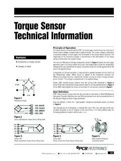
5 A Motor with higher flexibility would be more desirable for such applications. torque Tr Manufacturers, depending upon market needs, may adopt all or a few such designs or even have their own designs, still conforming to such stipulations. Special applications may, however, call for a custom-built Motor as noted later. As a standard practice all MV motors are S. custom-built for each application and no rotor designs Speed are prescribed for these. Nr Tst : Starting torque Tm : Pull-in or pull up torque Tpo : Pull-out or breakdown torque (maximum torque ). Tr : Rated torque Figure Defining a Motor torque *NEMA National Electrical Manufacturers' Association, USA. 2/44 Electrical Power Engineering Reference & Applications Handbook % Speed and the rotor current is carried into two parallel paths 0 20 40 60 80 100 made of these two cages, having a low effective resistance, 280 being in parallel.
6 In such designs, therefore, the speed . 260 torque curve can be achieved to take any desired shape De 240. sig n by suitably choosing the resistances of the two cages, the D width of the slot opening and the depth of the inner cage. nA. 220 sig The equivalent circuit diagram of a Motor with a single De 200 De and a double cage rotor is illustrated in Figure (a) and s ign C (b) respectively. To draw the speed torque curve for such 180. a Motor theoretically, consider the two cages developing 160 nB two different torques separately. The effective torque will sig De be the summation of these two, as shown in Figure 140. % torque 120. Notes 100 1 The inner and outer cages are separated by a narrow slit to facilitate linking of the main flux with the inner bars which are 80. quite deep.
7 60 2 MV motors are also manufactured with double cage rotors. They are designed especially to match a particular load 40 requirement when the load characteristics are known, or as in 20 NEMA class C, or as the manufacturer's own practice, when the starting torque requirement exceeds 150% of the full- load 0 torque (FLT). The likely applications for a high starting torque 100 80 60 40 20 0 may be induced-draught fans, blowers, coal crushers, mill % Slip motors and coal conveyor motors . 3 Generally, depending upon the type of load , different Figure Speed torque characteristics of motors as per manufacturers may adopt to different design practices, such as NEMA standard high Tst and low thermal withstand time or moderate Tst and high thermal withstand time. Special designs of rotors Ir R1 X1.
8 Double squirrel cage motors In . If the torque requirement of a load is high, an ordinary squirrel cage Motor , even on a DOL* switching, may not S SS X 2 . be suitable to meet the stringent starting requirements. Vr If, however, the resistance of the rotor circuit is increased the starting torque can be improved as discussed in Section . Im Im R 2 . (Equation ( )). But high rotor resistance will mean S. high running slip, causing greater rotor losses and heat in the rotor circuit. The solution to this problem is found in a double squirrel cage Motor . In such motors the rotor has two cages, one closer to the periphery of the rotor Figure (a) Equivalent circuit diagram of a single squirrel and the other deeper and nearer to the core. cage Motor The one closer to the periphery has a high resistance and the one nearer to the core a low one.
9 To accomplish Ir R1 X1. a high rotor resistance, high-resistivity materials such as brass is generally used. The inner cage has a high leakage In . reactance due to its depth, while the outer one has a high resistance and a low reactance like an ordinary squirrel S SS X 2 S SS X 2 . cage rotor. During start-up the inner cage has a very high impedance Vr and thus, the larger portion of the current passes through the outer cage only. Because of high resistance and high . Im Im R 2 R 2 . I2R loss in the rotor circuit, it develops a high starting S S. torque and accomplishes an analogue to a slip-ring Motor . When the rotor reaches the rated speed, the reactances of both the cages are almost negligible because of low slip 1st cage 2nd cage Figure (b) Equivalent circuit diagram of a double squirrel * DOL Direct On-Line.
10 Cage Motor Motor torque , load torque and selection of motors 2/45. Leakage Leakage flux flux Tst > Tpo Tst c=a+b Cumu lative torq ue c torque Outer ca ge high R b Tr (a) Deep bar (b) Taper bar (c) Double cage Inner cage low R a Figure Different types of rotor slots, making use of skin effect Speed Nr Figure Speed torque characteristics of a double squirrel cage Motor Outer cage, High R 2. Low X2. Performance In such motors the pull-out torque is normally less than Inner cage, the starting torque . This is because the pull-out torques Low R2. by the two cages occur at different speeds. Such motors High X2. would possess a low power factor and efficiency compared to an ordinary squirrel cage Motor , because of the high Figure Other designs of a few double cage slots leakage reactance of inner cage and comparatively higher I2R losses.