Transcription of Mounting and Assembly of Sandwich Bodies - Sun Hydraulics
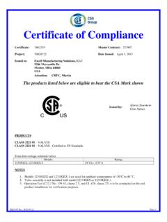
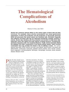
1 Sandwich Body Tech Tips: Web #999-90 -408 Rev. 0 -APR- 5 20 0 Sun Hydraulics CorporationSun Hydraulics Technical TipsMounting of ISO 03 (CETOP 3) SandwichesMany of Sun s ISO 03 (CETOP 3) Sandwich Bodies are designed for multi-functional use to permit maximum circuit flexibility. With the exception of a limited range of Sandwich Bodies , Sun ISO 03 (CETOP 3) Sandwich Bodies do not have a counterbore for installing O-ring seals. Instead, Sun uses a special seal plate with a raised NIB and a locating NOTCH . Sun Bodies incorporate oversize, symmetrical Mounting holes to allow the Bodies to be rotated about the Y axis and the X axis as shown in Figure.
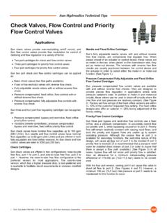
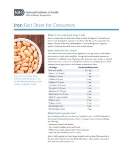
2 Rotation about the Y axis enables the A and B port connections to be interchanged and rotation about the X axis enables the P and T ports to be Sun seal plates are manufactured to accommodate current industry standards regarding port and Mounting bolt locations. Each Sun ISO 03 (CETOP 3) Sandwich body is supplied with a NIB locating hole which is drilled on each Mounting face to position the body in the correct relationship to the ports and Mounting holes. To further ensure that all Bodies are located properly, all ISO 03 (CETOP 3) Sandwich Bodies are stamped with an arrow (or arrows) to show the relationship to the notch in the seal plate (see Figure 2).
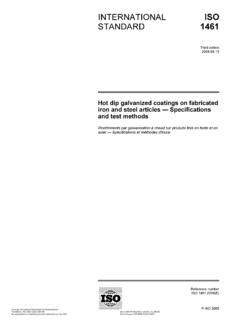
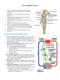
3 Multi-function Bodies are NOTCH stamped for all possible Mounting positions and all positions should be carefully inspected to be sure the intended function is correctly 03 (CETOP 3) Sandwich Bodies stamped with numbers to orient body for desired functionThe function symbols on the data pages for Sun s ISO 03 (CETOP 3) Sandwich Bodies (see Figure 3 on page 2) are shown with numbers (1,2,3,4) in the upper right and lower left hand corners. These numbers correspond to numbers stamped on the face of the Bodies and designate the functionality of the product. Because many of these Bodies can be used for different functions, the Bodies are stamped to help the user orient the body for the function desired.
4 The Meter-out A and Meter-in B functions are shown in the symbols with the numbers 3 and 4, which correspond to the numbers stamped on the opposite face of the of ISO 03 (CETOP 3) SandwichesPlace the seal plate on the subplate Mounting surface with the nib facing outward or away from the subplate and the locating pin hole on the seal plate aligned with the pin hole on the subplate Mounting surface. At this point, the NOTCH in the seal plate should be adjacent to the P port of the valve interface. See Figure .Position the Sun Sandwich body so that the control NOTCH arrow for the required function points to the NOTCH in the seal plate. See Figure the Sandwich body as required to engage the NIB on the seal plate with the clearance hole in the body.
5 NOTE: In every installation, the seal plate nib must be oriented toward the directional control valve and away from the subplate or manifold. All locating NIBS in the Sandwich valve stack must point away from the determining the correct alignment of the Sandwich body to the seal plate, lift the body and plate together, turn offers Sandwich and subplate mounted Bodies for most of its cartridge functions. These Mounting configurations are complete circuit elements that mount under directional control valves. Similar to other Sun Mounting configurations, the Sandwich and subplate Bodies are available in aluminum and ductile iron and Assembly of Sandwich BodiesFigure 1. Body Rotation Reference50 (12,7mm) Diameter, 4 Places for -- 012 O-rings 20 (5,1mm) Diameter, 4 Places X Rotation Axis Y RotationAxisLocating Pin Hole NOTCH.
6 05 (1,27mm) .04 (1,0mm) Locating PinRotation on the Y Axis X Rotation AxisTABPF igure 2. AssemblyMeter-in A NOTCH NIBA ssemblySunSandwichValveLocking PinSun Seal PlateSubplate or ManifoldSandwich Body Tech Tips: Web #999-90 -408 Rev. 0 -APR- 5 20 0 Sun Hydraulics Corporation 2 Sun Hydraulics Technical TipsPBAT1243 PBATF igure 3: Steps 1 through 4: Orientation Example for ISO 03 (CETOP 3) Sandwich Body GBASTEP 1 STEP 2 Begin with body view showing stamped number 1 in lower left corner. Note the location of P, T, A, and B ports and the position of the cavity. This position places the P port of the Sandwich nearest to the viewer. The Sandwich is now oriented for the meter out B B FunctionNote that the numbers on thefunction symbol for GBAcorrespond to the numbersstamped on the body.
7 Rotate the Sandwich on the X axis to orient body for meter-in B that the numbers on thefunction symbol for GBAcorrespond to the numbersstamped on the B Functionthe Assembly over and locate the correct hole in which to press the locating pin. The locating pin is shipped separately. Press the pin, serrated end first, into the body until it stops. The pin must protrude below the seal plate to positively align with the Mounting surface. If a valve stack requires disassembly at anytime, the pin should not be removed. It will simplify the reassembly of the valve stack. NOTE: Not all manufacturers of subplates offer a pin clearance hole which requires the pin to be all the body alignments have been determined and all pins installed, assemble the valve stack in the required functional order.
8 Make sure all the O-rings are properly positioned. Install the directional control valve on top of the stack and tighten the stud nuts alternately to the proper torque of 40-45 (4,5 5,0 Nm). to Avoid Seal Plate Leaks Make sure the Mounting surface is flat and without not polish the Mounting surface. (Machining marks help to keep the O-rings from acting as pumps.)Remove any dings on the corners of seal plates that could create or cap screws must not bottom out in the threaded Mounting is very important to keep all of the o-ring sealing surfaces dry . The hydrostatic properties of an oil film under the o-rings, and at the seal plate interface, can 3 STEP 4 APTBPinNIBNOTCH12 Rotate the Sandwich on the X axis to orient body for meter-in A that the numbers on thefunction symbol for GBAcorrespond to the numbersstamped on the A FunctionPABT2121 PinATPBNIBNOTCHAPTBPinNIBNOTCH43 Rotate the Sandwich on the Y axis to orient body for meter-out A that the numbers on thefunction symbol for GBAcorrespond to the numbersstamped on the A FunctionPABT43 NIBNOTCHPinBPTA433 Sandwich Body Tech Tips: Web #999-90 -408 Rev.
9 0 -APR- 5 20 0 Sun Hydraulics CorporationSun Hydraulics Technical Tipscreate a fluid path leading from the pressurized port to the outside edge of the stack. (Under this condition, as noted in step , an O-ring can actually act as a pump .) Warning: If you start with a wet seal interface in your stack, there s a good chance it will always stay wet! Orientation Example for ISO 03 (CETOP 3) bodiesSteps 1 through 4 in Figure 3 on page 2 describe in detail the steps for the orientation of a GBA Sandwich body. Mounting ISO 05 (CETOP 5) Sandwich Bodies Sun ISO 05 (CETOP 5) Sandwich Bodies are available formany Mounting configurations. The standard ISO05 (CETOP 5)/NFPA D05 is offered with two methods of sealing the fluid interface.
10 The sealing method depends on the ability of the body to be rotated about its Y axis. Sandwich Bodies that can be rotated will use a Sun seal plate supplied with the body. Non rotating Bodies will havecounterbores machined into the body sealing surfacefor O-ring placement. The ISO 05 (CETOP 5) Sandwich body can only be rotated about the Y axis referred to in the ISO 03 (CETOP 3) Sandwich section. (There is no NIB on the ISO 05 (CETOP 5) subplate,) X axis rotation is not possible due to the lack of symmetry of the fluid ports. Mounting ISO 05 (CETOP 5) x, y Sandwich BodiesSun ISO 05 (CETOP 5) x, y Sandwich Bodies are furnished with pilot and drain connections.