Transcription of MSD Power Grid System Controller PN 7730/77303
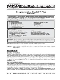
1 MSD (915) 855-7123 FAX (915) 857-3344 Parts Included:1 - System Controller , PN 7730 / PN 773031 - 4Gb SD Card1 - Micro-USB Cable1 - MSD View CD-Rom1 - Fiber Optic PlugWARNING: During installation, disconnect the battery cables. When disconnecting, always remove the Negative cable first and install it last. Note: Solid core spark plug wires cannot be used with an MSD Ignition Control. Note: A crank trigger is recommended to supply the input signal to the Power Grid Ignition System to ensure the most precise timing and rpm Power Grid System ControllerPN 7730/773031 - CAN Terminator Cap1 - Power Cable-Loose1 - Mag Cable1 - 2-pin Legacy Cable1 - Main Cable Loose1 - Parts Bag OPERATIONDIGITAL OPERATIONThe MSD Power Grid System Controller uses a high speed RISC microcontroller to control the ignition s output while constantly analyzing the various inputs such as launch, burnout, and step wires; trigger signals, rpm, and CAN-Bus data.
2 The high speed Controller can make extremely quick updates to the ignition output, timing, and rpm limits while maintaining +/- timing and +/- 1 rpm resolution. The circuits and Controller of this System have been designed for superior protection against Electro Magnetic Interference (EMI).The Power Grid System Controller , PN 7730 / PN 77303, is designed to be used with the Power Grid-7 Ignition Control, PN 7720. This is a high output CD ignition control. The Ignition System allows for the System Controller to be mounted on top of the Power Grid-7 to save space and provide a neat, compact installation. The System Controller can also be used with other MSD Ignitions such as the 7AL-2, MSD 8-Plus, and the Pro-Mag series. In order to use the rev limiting features of the System Controller the paired ignition must have a built-in Soft Touch Rev Control that uses plug-in RPM modules.
3 Pages 10-12 show wiring diagrams for a variety of different ignition (Purchased Separately): Inductive Cam Sync Kit, PN 7555 Hub Connector, PN 7740 / PN 77403 Slew Rate and Time Based Rev Limiter, PN 7761 Boost Retard Module, PN 7762 Manual Launch Controller , PN 7751 Racepak V-Net Tee9 - 280-CA-VM-T00918 - 280-CA-VM-T01836 - 280-CA-VM-T036 ONLINE PRODUCT REGISTRATION: Register your MSD product online. Registering your product will help if there is ever a warranty issue with your product and helps the MSD R&D team create new products that you ask for! Go to INSTALLATION INSTRUCTIONSMSD (915) 855-7123 FAX (915) 857-33444-Pin Connector (to PN 7720 or Power Cable if not used with PN 7720)LOOSEWIRES2-Pin Connector (Legacy)3-Pin ConnectorRacepak Assembly6-Pin Connector (to Hub/Modules)Color PIN Function DescriptionBLACK 16 GROUND Ignition supply Ground wire.
4 Connect to battery negative (-) terminal or engine 17 BATT Power Battery supply wire. Connects to battery positive (+) terminal or battery junction. Note: Do not connect to the 33 TRIGGER OUT Trigger output for electronic ignition 34 Power OUT On/Off switch wiring. This wire supplies switched 12V Power to the 7720. RED 15 IGN 12V switched (Ignition)GRAY 18 TACH Tach output. This wire will provide a 12 volt square wave tach 32 POINTS IN Trigger input from electronic ignition amplifiers, an ECU s trigger or 1 SHIFT LIGHT Shift Light output wire. It can handle up to 3 amps continuous to ground when BLUE 4 BURN OUT Burnout Rev Limit. When 12 volts are applied the Burnout Rev Limit is active. This disables the Slew Rate rev limits and overrides other rev limits.
5 It is recommended to have this wire switched from an outside source, such as the crew chief before the burnout and while staging the BLUE 21 LAUNCH This wire activates the Launch Rev Limit and is the main reset wire for several features of the Ignition. When 12 volts are applied to this wire it will activate the Launch Rev Limit. It also resets the shift light, the gear indicator to first gear, the Launch Retard curve and select Gear 1 curve. When 12 volts is removed, the Launch Time begins as does the Gear 1 curve. When 12 volts are applied the Slew Rate Rev limit will be disabled as well as the Time-Based Rev Limit 22 STEP 1 Step 1 retard enabled with +12 volt input AND above Step 1 Rpm value OR Gear 2 5 STEP 2 Step 2 retard enabled with +12 volt input AND above Step 2 Rpm value OR Gear 3 23 STEP3 Step 3 retard enabled with +12 volt input AND above Step 3 Rpm value OR Gear 4 GREEN 6 STEP4 Step 4 retard enabled with +12 volt input AND above Step 4 Rpm value OR Gear 5 10 STEP5 Step 5 retard enabled with +12 volt input AND above Step 5 Rpm value OR spool rev 19 RPM SW RPM/Time switch output wire.
6 It can switch up to 3 amps continuous to ground when enabled. YELLOW 7 RELAY LO Network Ignition Mode: Cam sync output to Racepak systems for individual cylinder 24 RELAY HI Legacy Ignition Mode: Rev limiter output to legacy GREEN 8 MAG- VIOLET 9 MAG+ BROWN 25 SHIELD WHITE 11 VNET HI BLACK VNET LO RED 13 MSD CAN HI This i s a magnetic pickup, 2-pin connector. Plugs into a n MSD Distributor or Crank Trigger pickup. Violet is positive, Green is negative. Note: When this connector is used, the white POINTS IN wire is not connected. Brown connects to data acquisition information with RacePak System . Only used to plug into VNet. Supplies 12V switched Power to add on module units. Also communicates between modules and Power Grid System Controller .
7 This connector plugs into CAN-Bus hub, PN 7740/77403 to add additional modules. If not used plug in a Termination Cap, PN 27 SHIELD RED 29 Power OUT BLACK 30 MSD CAN LO BLACK 31 MSD CAN GND LeadingGroupWireorWIRING FEATURESINSTALLATION INSTRUCTIONS 3 MSD (915) 855-7123 FAX (915) 857-3344 RED - 12V SW OUTBLACK - BATTERY (-)ORANGE - BATTERY 12 VWHITE - POINTS OUTMSDCANMAG PICKUPCONNECTORLEGACY IGNITIONSWITCHED IGNITION 12 VGREEN - STEP 5LT. GREEN - STEP 4 TAN - STEP 3 VIOLET - STEP 2 PINK - STEP 1 BLUE - LAUNCHLT. BLUE - BURN OUTBRN/WHITE - RPM/TIME SWITCHWHITE - POINTS INGRAY - TACHYELLOW - SHIFT LIGHTV-NETCABLEF igure 1 Wires of the Power Grid System Controller . Figure 2 Wiring the Power : SEE PAGES 10-12 FOR SCHEMATICS SHOWING INSTALLATION TO OTHER MSD IGNITION - 12V SW OUTBLACK - BATTERY (-)ORANGE - BATTERY 12 VWHITE - POINTS OUTMSDCANMAG PICKUPCONNECTORLEGACY IGNITIONSWITCHED IGNITION 12 VGREEN - STEP 5LT.
8 GREEN - STEP 4 TAN - STEP 3 VIOLET - STEP 2 PINK - STEP 1 BLUE - LAUNCHLT. BLUE - BURN OUTBRN/WHITE - RPM/TIME SWITCHWHITE - POINTS INGRAY - TACHYELLOW - SHIFT LIGHTPN 7720 IGNITIONORANGEBLACK++--TO BATTERY POSITIVETO BATTERY NEGATIVEHEAVY REDHEAVY BLACKV-NETCABLEVNET Connector4-Pin Deutsch connector3-Pin Deutsch connector4-Pin Deutsch connector FemaleVN7730 HarnessConnectorsMating Pieces If any3-Pin Deutsch connector Female4 INSTALLATION INSTRUCTIONSMSD (915) 855-7123 FAX (915) 857-3344 MOUNTINGThe Power Grid System Controller should be mounted in a sturdy, dry location that does not expose the unit to extreme heat. It is designed to be mounted on top of the PN 7720 Power Grid Ignition. Be sure to mount the Power Grid System Controller so the USB connector and Micro-SD card are accessible.
9 The unit comes with thread-turning (aka. Self-tapping) screws that will cut into the walls of the pre-drilled holes on the top corners of the Power Grid-7. If the Power Grid System Controller , PN 7730 / PN 77303, is not being mounted on top of the Power Grid-7 the unit should be secured with the supplied : Insecure or otherwise improper mounting of the unit could result in damage or failure. Always make sure the unit is dry, avoids unnecessary excess vibration, and is not exposed to extreme VIEW The MSD View software controls all of the functionality of the Power Grid System Controller . The following information gives a brief explanation of each function or feature in the System as well as the settings that control it. While using the program, hover the mouse over a Function to display a brief explanation.
10 When the System Controller is connected to a PC via USB MSD View will automatically recognize it and load the settings stored in : Ensure that MSD View is installed on the PC prior to connecting the Power Grid Ignition OF THE VIEW SOFTWARE1. Insert the installation CD Rom into the CD drive, wait up to 30 seconds, the CD will auto run, IF THISDOES NOT OCCUR:Locate and open the CD click on the Setup Select Click here to Install Version .3. Once loaded, your monitor will have an MSD View logo. Accept the agreement. Drive the installationto your program files folder, press the enter key. The installation will complete, select A window will be opened with two aliases, double-click on the MSD View alias to launch the Connect the System Controller via USB. If the software does not recognize the Controller and auto-connect,manually select the Power Grid in the popup window and click : The View Software can be downloaded from AND TRANSFERSU sing the Power Grid System Controller changes are in real time if the computer is linked to the can create and save numerous files on your PC and transfer them for testing purposes or to use for various locations and following instructions will go through a general description of the use of the Power Grid System Control following the tab System that you will see in the 3 MountingINSTALLATION INSTRUCTIONS 5 MSD (915) 855-7123 FAX (915) 857-3344 PROGRAMMABLE FEATURES AND SETTINGS:GENERALT hese are the most basic settings of the System .