Transcription of Multifunction controller …
1 DIXEL Installing and Operating Instructions 1592007500 1592007500 XR10-20-40-60 E-class GB XR10C - XR20C XR40C XR60C 1/3 Multifunction controller XR10C/XR20C/XR40C/XR60C E - Class CONTENTS 1. GENERAL WARNING _____1 2. GENERAL DESCRIPTION _____1 3. CONTROLLING LOADS _____1 4. FRONT PANELS _____1 5. PARAMETERS _____2 6. INSTALLATION AND MOUNTING _____3 7. ELECTRICAL CONNECTIONS_____3 8. ALARM SIGNALS _____3 9. TECHNICAL DATA _____3 10. CONNECTIONS _____3 11. DEFAULT SETTING VALUES _____3 1. GENERAL WARNING PLEASE READ BEFORE USING THIS MANUAL This manual is part of the product and should be kept near the instrument for easy and quick reference. The instrument shall not be used for purposes different from those described hereunder. It cannot be used as a safety device. Check the application limits before proceeding. SAFETY PRECAUTIONS Check the supply voltage is correct before connecting the instrument. Do not expose to water or moisture: use the controller only within the operating limits avoiding sudden temperature changes with high atmospheric humidity to prevent formation of condensation Warning: disconnect all electrical connections before any kind of maintenance.
2 Fit the probe where it is not accessible by the End User. The instrument must not be opened. In case of failure or faulty operation send the instrument back to the distributor or to Dixell (see address) with a detailed description of the fault. Consider the maximum current which can be applied to each relay (see Technical Data). Ensure that the wires for probes, loads and the power supply are separated and far enough from each other, without crossing or intertwining. In case of applications in industrial environments, the use of mains filters (our mod. FT1) in parallel with inductive loads could be useful. 2. GENERAL DESCRIPTION Models XR10C, format 32 x 74 mm is a single stage temperature controllers suitable for applications in the field of refrigeration or heating. It provides a relay output and a NTC probe input. The instrument is fully configurable through special parameters that can be easily programmed through the keyboard.
3 Model XR20C, format 32 x 74 mm, is thermostat with off cycle defrost designed for refrigeration applications at normal temperature. It has a relay output to drive the compressor and NTC probe input. A internal timer manages the off cycle defrost. The instrument is fully configurable through special parameters that can be easily programmed through the keyboard. Model XR40C, format 32 x 74 mm, is microprocessor based controller , suitable for applications on medium or low temperature refrigerating units. It has 2 relay outputs to control compressor and defrost, which can be either electrical or reverse cycle (hot gas). It is also provided with two NTC probe inputs, one for temperature control, the other, to be located onto the evaporator, to control the defrost termination temperature. The instrument is fully configurable through special parameters that can be easily programmed through the keyboard.
4 Model XR60C, 32x74 mm format, is a microprocessor based controller , suitable for applications on medium or low temperature ventilated refrigerating units. It has three relay outputs to control compressor, fan, and defrost, which can be either electrical or reverse cycle (hot gas). The instrument is fully configurable through special parameters that can be easily programmed through the keyboard. 3. CONTROLLING LOADS THE COMPRESSOR The regulation is performed according to the temperature measured by the thermostat probe with a positive differential from the set point: if the temperature increases and reaches set point plus differential the compressor is started and then turned off when the temperature reaches the set point value again. TimeTem In case of fault in the thermostat probe the start and stop of the compressor are timed through parameters COn and COF.
5 DEFROST XR20C-E Defrost is performed through a simple stop of the compressor. Parameter IdF controls the interval between defrost cycles, while its length is controlled by parameter MdF . DEFROST Two defrost modes are available through the tdF parameter: defrost through electrical heater (tdF = EL) and hot gas defrost (tdF = in). Other parameters are used to control the interval between defrost cycles (IdF), its maximum length (MdF) and two defrost modes: timed or controlled by the evaporator s probe (P2P). CONTROL OF EVAPORATOR FANS The fan control mode is selected by means of the FnC parameter: FnC = C_n: fans will switch ON and OFF with the compressor and not run during defrost; FnC = o_n fans will run even if the compressor is off, and not run during defrost; After defrost, there is a timed fan delay allowing for drip time, set by means of the Fnd parameter. FnC = C_Y fans will switch ON and OFF with the compressor and run during defrost; FnC = o_Y fans will run continuously also during defrost An additional parameter FSt provides the setting of temperature, detected by the evaporator probe, above which the fans are always OFF.
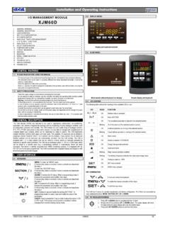
6 This is used to make sure circulation of air only if his temperature is lower than set in FSt . 4. FRONT PANELS SET: To display target set point; in programming mode it selects a parameter or confirm an operation. (DEF) To start a manual defrost o (UP): To see the max. stored temperature; in programming mode it browses the parameter codes or increases the displayed value. n (DOWN) To see the min stored temperature; in programming mode it browses the parameter codes or decreases the displayed value. KEY COMBINATIONS: o + n To lock & unlock the keyboard. SET + n To enter in programming mode. SET + o To return to the room temperature display. USE OF LEDS Each LED function is described in the following table. LED MODE FUNCTION ON Compressor enabled Flashing -Programming Phase (flashing with ) - Anti-short cycle delay enabled ON Defrost enabled Flashing - Programming Phase (flashing with ) - Drip time in progress ON Fans enabled (not for XR10-20) Flashing Fans delay after defrost in progress.
7 (not for XR10-20) HOW TO SEE THE MIN TEMPERATURE 1. Press and release the n key. dIXEL Installing and Operating Instructions 1592007500 1592007500 XR10-20-40-60 E-class GB XR10C - XR20C XR40C XR60C 2/3 2. The Lo message will be displayed followed by the minimum temperature recorded. 3. By pressing the n key again or by waiting 5s the normal display will be restored. HOW TO SEE THE MAX TEMPERATURE 1. Press and release the o key. 2. The Hi message will be displayed followed by the maximum temperature recorded. 3. By pressing the o key again or by waiting 5s the normal display will be restored. HOW TO RESET THE MAX AND MIN TEMPERATURE RECORDED 1. Hold press the SET key for more than 3s, while the max. or min temperature is displayed. (rSt message will be displayed) 2. To confirm the operation the rSt message starts blinking and the normal temperature will be displayed.
8 HOW TO SEE THE SETPOINT 1. Push and immediately release the SET key: the display will show the Set point value; 2. Push and immediately release the SET key or wait for 5 seconds to display the probe value again. HOW TO CHANGE THE SETPOINT 1. Push the SET key for more than 2 seconds to change the Set point value; 2. The value of the set point will be displayed and the LED starts blinking; 3. To change the Set value push the o or n arrows within 10s. 4. To memorise the new set point value push the SET key again or wait 10s. HOW TO START A MANUAL DEFROST Push the DEF key for more than 2 seconds and a manual defrost will start. HOW TO CHANGE A PARAMETER VALUE To change the parameter s value operate as follows: 1. Enter the Programming mode by pressing the Set and DOWN key for 3s ( and start blinking). 2. Select the required parameter. 3. Press the SET key to display its value (now only the LED is blinking). 4. Use UP or DOWN to change its value.
9 5. Press SET to store the new value and move to the following parameter. To exit: Press SET + UP or wait 15s without pressing a key. NOTE: the set value is stored even when the procedure is exited by waiting the time-out to expire. THE HIDDEN MENU The hidden menu Includes all the parameters of the instrument. HOW TO ENTER THE HIDDEN MENU 1. Enter the Programming mode by pressing the Set + n key for 3s (LED 1 and start blinking). 2. When a parameter is displayed keep pressed the Set+n for more than 7s. The Pr2 label will be displayed immediately followed from the HY parameter. NOW YOU ARE IN THE HIDDEN MENU. 3. Select the required parameter. 4. Press the SET key to display its value (Now only the LED is blinking). 5. Use o or n to change its value. 6. Press SET to store the new value and move to the following parameter. To exit: Press SET + o or wait 15s without pressing a key. NOTE: the set value is stored even when the procedure is exited by waiting the time-out to expire.
10 HOW TO MOVE A PARAMETER FROM THE HIDDEN MENU TO THE FIRST LEVEL AND VICEVERSA. Each parameter present in the HIDDEN MENU can be removed or put into THE FIRST LEVEL (user level) by pressing SET + n . In HIDDEN MENU when a parameter is present in First Level the decimal point is on. HOW TO LOCK THE KEYBOARD 1. Keep pressed for more than 3 s the UP and DOWN keys. 2. The POF message will be displayed and the keyboard will be locked. At this point it will be possible only to see the set point or the MAX o Min temperature stored 3. If a key is pressed more than 3s the POF message will be displayed. TO UNLOCK THE KEYBOARD Keep pressed together for more than 3s the UP and DOWN keys. 5. PARAMETERS NOTE: the parameters preceded by dots are only in the Hidden Menu. REGULATION Hy Differential: (0,1 25,5 C / 1 255 F) Intervention differential for set point. Compressor Cut IN is Set Point Plus Differential (Hy).